Installation – Lincoln Electric IDEALARC IM420-D User Manual
Page 12
A-5
INSTALLATION
IDEALARC® DC-1000
A-5
OUTPUT CONNECTIONS
Output Studs
The output leads are connected to the output termi-
nals. The output terminals are located on the lower
case front and labeled “+” and “-”. There are 1000
amp rated “+” terminals on the right side, one 500
amp rated “+” terminal near the center and “-” termi-
nals on the left side. They are fully recessed to mini-
mize the possibility of accidental contact by an object
or a person. Strain relief is provided by the oval holes
in the base. The leads are run through these oval
holes before they are connected to the output termi-
nals.
The 1000 amp output connections provide the full
rated output range of the machine. See Table1 for
recommended DC-1000 cable sizes for combined
lengths of electrode and work cables.
The 500 amp output connections provide enhanced
lower current arc characteristics, especially for sub-
merged arc and GMAW procedures below 450 amps.
Auxiliary Power
This machine supplies the 115 volt, AC power needed
for operating wire feeding equipment. The power is
available from terminals #31 and #32 on the terminal
strip. An 8 amp slow blow fuse on the machine control
panel protects the auxiliary power from excessive
overloads. The circuit has a 1000 volt-ampere rating.
Control Cable Connection
Terminal strips with screw connections are located
behind the hinged door on the front of the power
source to make all the control cable connections for
operating wire feeding equipment. See the appropri-
ate connection diagram for exact instructions covering
the wire feeder being used.
With the DC-1000 turned off, the control cable from
the automatic wire feeding equipment is connected to
the terminal strip. A strain relief box connector is pro-
vided for access into the terminal strip section. A
chassis grounding screw is also provided below the
terminal strip marked with the symbol for connect-
ing the wire feeding equipment grounding wire. See
the appropriate connection diagram for the exact
instructions for the wire feeder being used. A spare
hole is provided for an additional box connector if
required.
Connecting for Air Carbon Arc:
a. Turn off all power.
b. Disconnect all wire feed unit control, electrode and
work leads.
c. Connect a jumper from 2-4 on terminal strip.
d. Place mode switch in the CV(I) position.
With the DC-1000 connected for air carbon arc weld-
ing, the output terminals will be energized at all times.
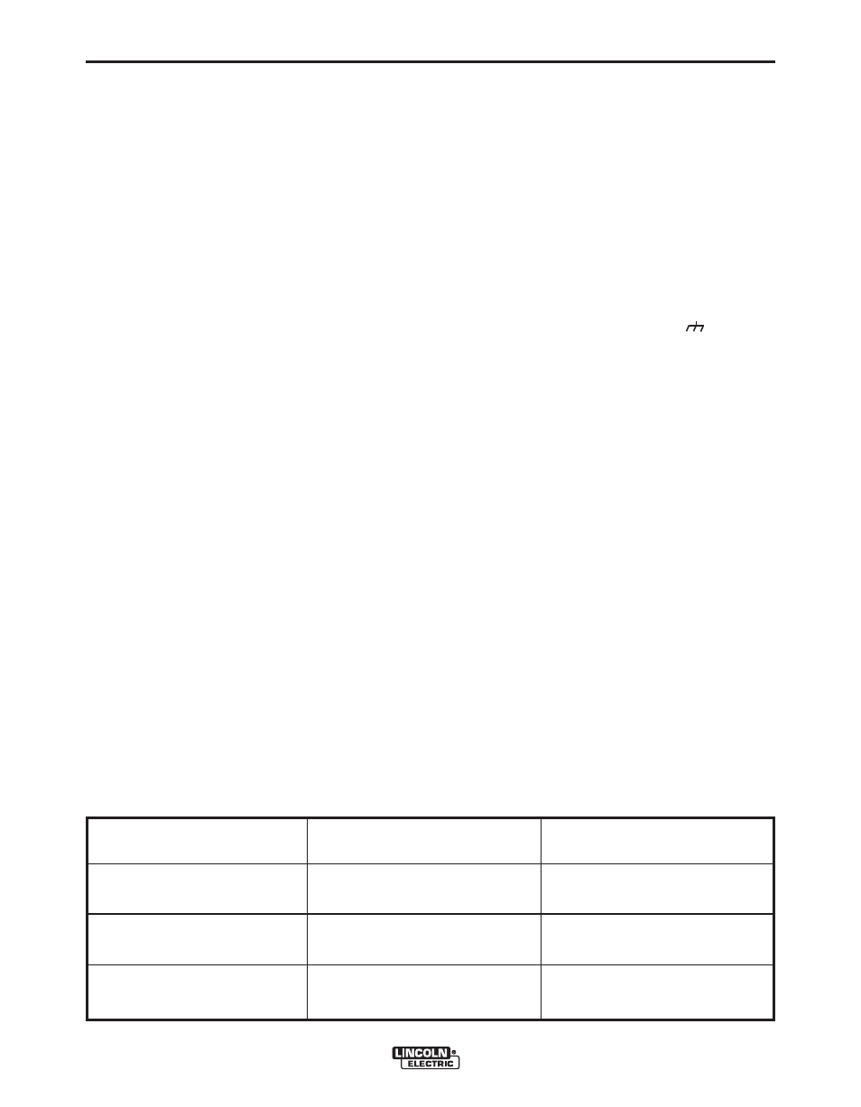
Cable Size
Parallel Cables
Cable Length
1/0 (53mm
2
)
3
3
3
Lengths up to 150 ft. (46m)
2/0 (67mm
2
)
150 ft.(46m) to 200 ft (61m)
3/0 (85mm
2
)
200 ft.(61m) to 250 ft.(76m)
TABLE 1
DC-1000 Cable Sizes for Combined Lengths of Copper Electrode and Work Cable
at 100% Duty Cycle
ELECTRODE, WORK AND #21 LEAD