System wiring overview, A. lcp128 panel – Lutron Electronics LCP128 User Manual
Page 9
R
Installation Guide for Dimming and Switching Panels 9
System Wiring Overview
S
ELECT
C
IRCUIT
2
1
Circuit
Data A OK
Power
1 2 3 4
5
D
Common
24VFW
MUX
MUX
Drain
Sense
1 2 3 4
D
5
B
Comm
Drain
MUX
MUX
C
D
Link
A
Link
C
D
Data B OK
Common
+24 V
MUX
MUX
Drain
Sense
Common
MUX
MUX
Drain
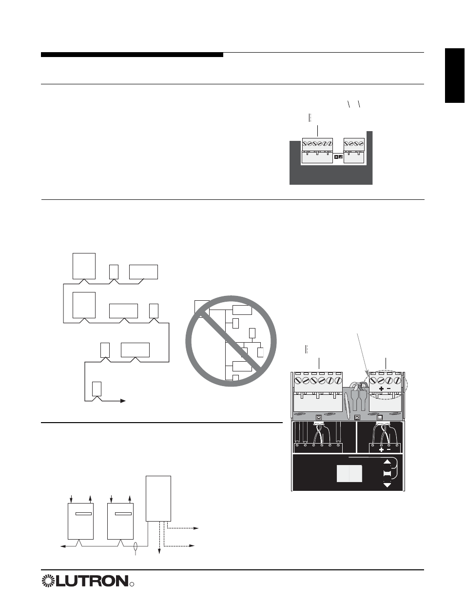
Note: Single-link circuit selectors
will not have Link B connector.
Review the options below for information on wiring your panel correctly into your specific system.
A. LCP128 panel:
Refer to the LCP128 Setup and Operation
Manual for detailed wiring information.
B. LP or CCP panel as a part of a GRAFIK
Eye 4000 lighting system:
Refer to the GRAFIK Eye
4000 Installation, Setup, and Operation Manual and the system
overview pictured here for detailed wiring information.
C. LP or CCP panel as a part of a GRAFIK
7000 lighting system:
Refer to the GRAFIK7000
Installation, and Maintenance Guide and the system overview
pictured here for detailed wiring information.
1 2 3 4 D 5
Contact closure input
(CCI) 1
Contact closure input
(CCI) 2
Common
+24 V
MUX
MUX
Drain
Sense
Common
Signal
Common
Signal
{
{
Controller Terminals
Circuit Selector Terminals
Incorrect: Branch, T-tap, or home run
not acceptable
Panel
Panel
To other panels,
GRAFIK Eye control
units, wallstations, or
control interfaces
Control
interface
GRAFIK
Eye
GRAFIK
Eye
Wallstation
Correct: Daisychain OK
GRAFIK
Eye
Control
interface
Wallstation
GRAFIK
5000,
6000, or
7000
panel
Power panel link
Control station device link
Lighting zone controller link
Integration to other devices
Power
panel
Power
panel