Panel with main lugs: load wiring, Connecting an ngrx-fdbi to a panel, Load wiring for tvm module – Lutron Electronics LCP128 User Manual
Page 15
R
Installation Guide for Dimming and Switching Panels 15
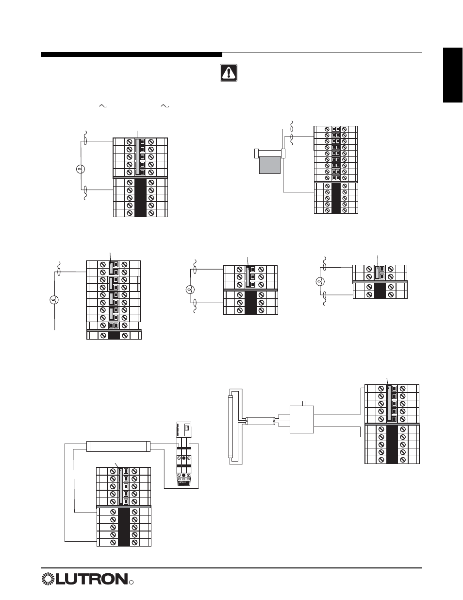
Panel with Main Lugs: Load Wiring
N
N
DH
H
N
N
DH
H
DH
N
N
N
DH
H
DH
N
DH
DH
N
N
H
N
H1
SH1
H2
SH2
H3
SH3
H4
SH4
N
N
L
H
R
N
L
R
N
N
L
R
L
R
Dimmed hot/live
Neutral
Load
Switched
hot/live
Neutral
Load
Dimmed hot/live
Neutral
Load
Dimmed hot/live
Neutral
Load
Raise
Lower
Shade
Neutral
1-Circuit Dimming Module (1U)
(LCP only)
2-Circuit Dimming Module (2U)
(LCP only)
4-Circuit Dimming Module (4U)
4-Circuit Adaptive Dimming Module (4A)
4-Circuit ELV Dimming Module
(4E: 230 V
and 220-240 V
only)
4-Circuit Fan Speed Control Module (4FSQ)
4-Circuit Switching Module
(XP)
4-Circuit Motor Module
(4M)
Bypass jumper
Bypass jumper
Bypass jumper
Bypass jumper
LUTRON
®
LUTRON
®
N
N
DH
H
DH
N
DH
DH
N
N
Connecting an NGRX-FDBI to a Panel
For Hi-Lume
®
FDB or Eco-10
TM
Fluorescent Dimming Ballast
Load
Eco-10 or
Hi-Lume
FDB ballast
Neutral
Dimmed
hot/live
FDBI
Feed
Load Wiring for TVM Module
For 0-10 V, PWM, and Tridonic
®
DSI loads. Each
TVM controls two consecutive circuits of lighting and
are the first circuits in the panel. Maximum low-
voltage ballast control current:
50 mA per zone, 750 mA per panel.
+ 1 –
+ 2 –
L
N
+
–
N
N
DH
H
DH
N
DH
DH
N
N
Ballast
Neutral
Dimmed
hot/live
TVM
Caution! Do not remove bypass jumpers until after
load wiring has been verified.
Typical Dimming/Switching Leg Shown
Bypass jumper
Bypass jumper