Lutron Electronics LCP128 User Manual
Page 12
R
12
Installation Guide for Dimming and Switching Panels
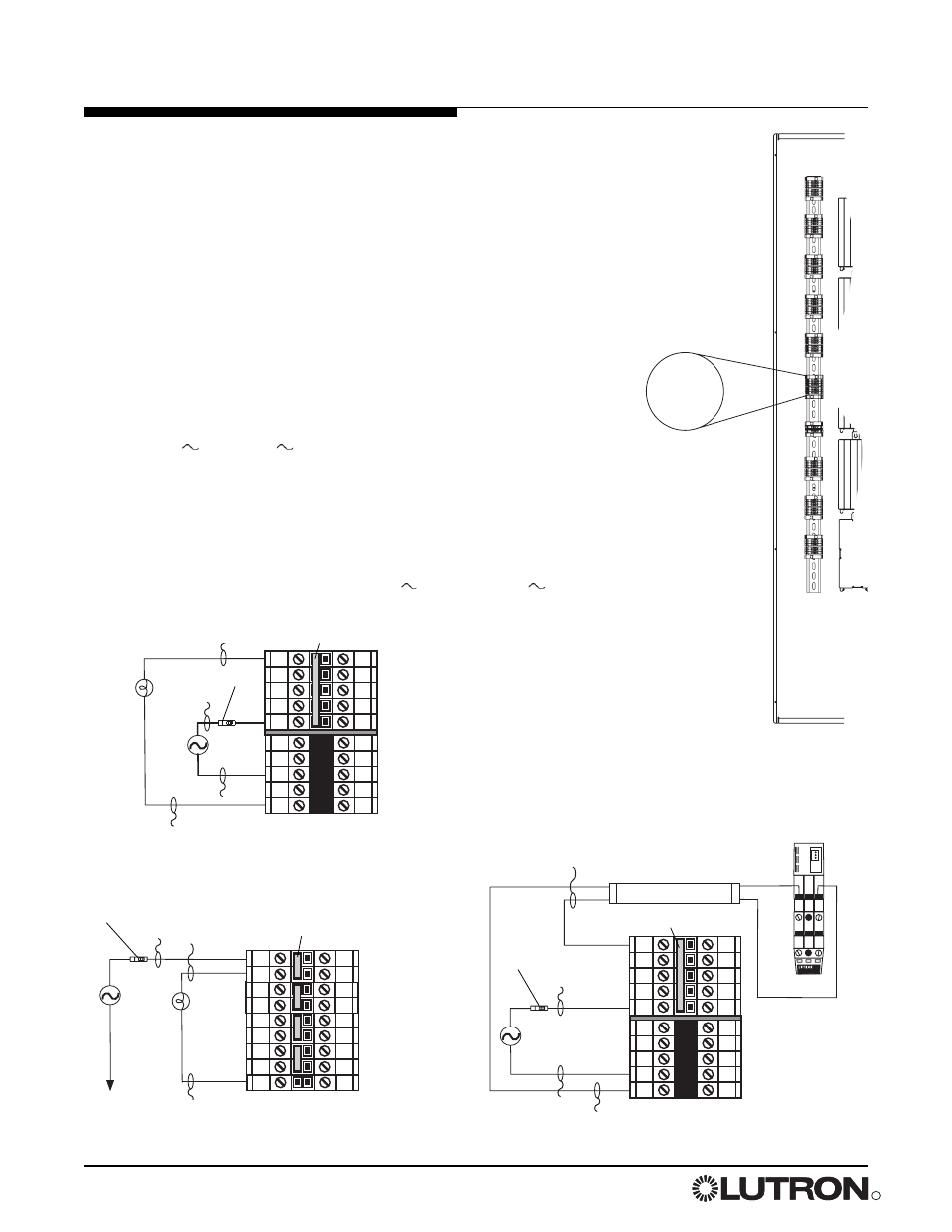
Feed-Through Panel: Feed and Load Wiring (all voltages)
N
N
DH
H
DH
N
DH
DH
N
N
N
H1
SH1
H2
SH2
H3
SH3
H4
SH4
To distribution
panel
Load
Neutral
Hot/live
Switched
hot/live
Dimmed hot/live
Hot/Live
Neutral
Neutral
Load
4-Circuit Dimming Module (4U)
4-Circuit Adaptive Dimming Module (4A)
4-Circuit ELV Dimming Module (4E: 230 V
and 220-240 V
only)
4-Circuit Quiet Fan Speed Module (4FSQ)
4-Circuit Switching (Relay) Module (XP)
Bypass jumper
Bypass jumper
Bypass
jumper
Feed
Feed
Feed
TVM Module
For 0-10 V, PWM, Tridonic
®
DSI, and DALI loads. Each TVM
controls two consecutive circuits of lighting and are the first
circuits in the panel. Maximum low-voltage ballast control
current: 50 mA per zone, 750 mA per panel. Dimming or
switching module is used to switch power to the ballast.
+ 1 –
+ 2 –
N
H/L
+
–
N
N
DH
H
DH
N
DH
DH
N
N
Ballast
Neutral
Neutral
Hot/Live
Dimmed hot/live
TVM
General Notes
• Typical dimming/switching legs shown.
• Do not remove bypass jumpers until after load wiring has been verified.
Wire sizes for power feed, to each input
• Power feed: #14 AWG (2.5 mm
2
) to #10 AWG (4.0 mm
2
)
• Neutral feed: #14 AWG (2.5 mm
2
) to #10 AWG (4.0 mm
2
)
Wire sizes for load wiring, from each output
• Dimmed hot (live): #14 AWG (2.5 mm
2
) to #10 AWG (4.0 mm
2
)
• Load neutral: #14 AWG (2.5 mm
2
) to #10 AWG (4.0 mm
2
)
Control Circuit Power
• Supplies power for internal operation.
• Requires dedicated feed with same voltage and phase as panel.
• Must be 1/4 in. (6 mm) away from PELV (Class 2: USA) control wiring
harness.
• Panel voltage (see pages 2-3) indicates feed voltage.
• For 230 V
and 240 V
panels, “Hot” is referred to as “Live”.
Therefore, terminals will be labeled L and DL.
See terminal block
modules for
specific wiring
details.
Circuit breaker
Circuit breaker
Circuit breaker