Troubleshooting – Lochinvar KNIGHT 399 User Manual
Page 32
3
Troubleshooting
32
Service Manual
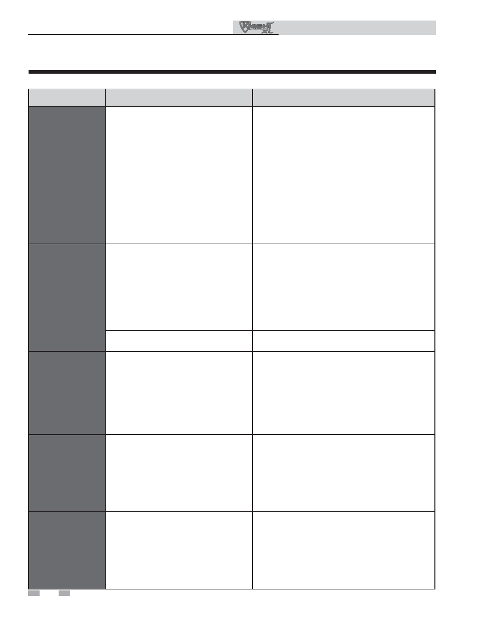
Table 3F Troubleshooting Chart - Fault Messages Displayed on Boiler Interface
FAULT
DESCRIPTION
CORRECTIVE ACTION
Gas Pressure SW
(will require a manual
reset once the condition
has been corrected.
Press the RESET button
on the SMART SYSTEM
display to reset.)
Either the optional manual reset low gas
pressure switch or the optional manual reset
high gas pressure switch tripped (not
available on 399 models).
• Reset the pressure switches.
• Measure the supply gas pressure to determine cause
of failure. Natural gas pressures should be between
4 - 14 inches w.c. (1.0 - 3.5 kPa) and LP gas
pressures should be between 8 - 14 inches w.c.
(2.0 - 3.2 kPa).
• Refer to Section 7 - Gas Connections of the Knight
XL Installation and Operation Manual for detailed
information concerning the gas supply.
• Correct the supply gas pressure if necessary.
• Check for a loose or misplaced jumper if pressure
switches are not installed.
Flow
Switch/LWCO
(will require a manual
reset once condition has
been corrected. Press
the RESET button on
the SMART SYSTEM
display to reset.)
Either the flow switch or the optional low
water cutoff is not making.
• Check boiler pump operation on a call for heat.
• Check for closed valves or obstructions in the boiler
piping.
• Verify system is full of water and all air has been
purged from the system.
• Check for loose or misplaced jumpers if flow switch or
LWCO is not installed.
Blown fuse.
• Replace fuse F2 on the control board, see page 28 of
this manual.
Blocked Drain SW
(will require a manual
reset once condition has
been corrected. Press
the RESET button on
the SMART SYSTEM
display to reset.)
The blocked drain switch has detected
excessive condensate build up inside the
unit.
• Check condensate tube from unit to floor drain for
proper installation and obstructions.
• Inspect condensate trap for blockage. Clean if
necessary.
• Check for loose wiring connection at wire harness
plug.
• Bad blocked drain switch. Replace switch.
Flame
Sequence
(will require a manual
reset once the condition
has been corrected.
Press the RESET button
on the SMART SYSTEM
display to reset.)
The flame detector circuit is seeing a flame
signal while no flame is present.
• Check supply voltage for proper polarity.
• Check external wiring for voltage feedback.
• Check the flame rod and make sure it is clean.
• Check the internal wiring for bad connections.
• Replace main control board.
GV/Relay
Fail
(will require a manual
reset once the condition
has been corrected.
Press the RESET button
on the SMART SYSTEM
display to reset.)
The main control board did not detect the gas
valve.
• Check wiring harness connection at the gas valve and
at the main control board.
• Replace the gas valve wire harness.
• Replace the gas valve.
• Replace the main control board.