Service, Parameter table, Service manual – Lochinvar KNIGHT 399 User Manual
Page 16
1
Service
16
Service Manual
1
Service
Parameter table
(continued)
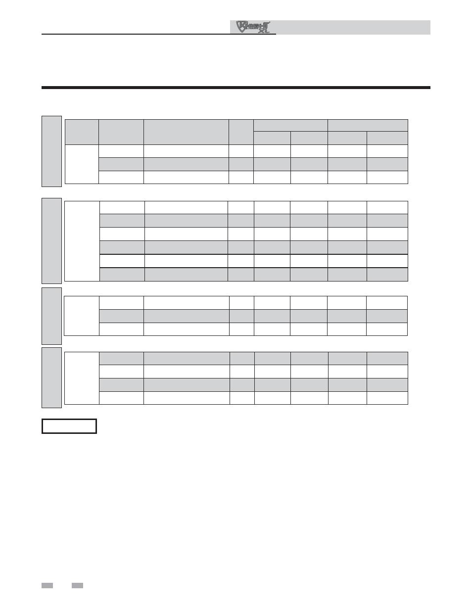
Table 1D (continued from previous page) This table lists SMART SYSTEM control module parameters and
where to access them
The parameters for Building Management System operation are not listed in this table. They are only
accessible using the PC interface software. See separate documentation for access information. See page
21 of this manual for a brief discussion.
NOTICE
MENU
SUB ITEM
DESCRIPTION
SEE
PAGE
USER ACCESS
INSTALLER ACCESS
DISPLAY MODIFY DISPLAY
MODIFY
G
1
Anti-cycling Time
20
No
No
Yes
Yes
2
Return Temperature Differential
for Ending Anti-Cycling
20
No
No
Yes
Yes
3
Ramp Delay On/Off
20
No
No
Yes
Yes
ANTI-CYCLING
H
1
SH Controlling Sensor
(Outlet/System, Inlet)
21
No
No
Yes
Yes
2
SH Source (Thermostat, BMS,
and Cascade)
21
No
No
Yes
Yes
3
Boiler Cascade Address
21
No
No
Yes
Yes
4
Max. Cascade Set Point
21
No
No
Yes
Yes
5
Cascade Offset
22
No
No
Yes
Yes
6
Cascade Differential
22
No
No
Yes
Yes
CONTROL
MODES
I
1
System Pump Delay
22
No
No
Yes
Yes
2
SH Pump Delay
22
No
No
Yes
Yes
3
DHW Pump Delay
22
No
No
Yes
Yes
CIRCULATION
PUMPS
J
1
Service Notification in Month
22
No
No
Yes
Yes
2
Service Notification Running
Hours
22
No
No
Yes
Yes
3
Service Notification Boiler Cycles
22
No
No
Yes
Yes
4
Reset Service Notification Counter
22
No
No
Yes
Yes
SERVICE
NOTIFICATION