Lennox International Inc. MERIT PLUS MPB3530CNM-B User Manual
Page 7
7
NOTE: DIAGRAMS & ILLUSTRATIONS ARE NOT TO SCALE.
LENNOX HEARTH PRODUCTS • MERIT PLUS
®
B-VENT GAS FIREPLACES (MPB33/35/40/45) • INSTALLATION INSTRUCTIONS
PRE-INSTALLATION STEPS
The appliance is shipped with all gas controls
and components installed and pre-wired.
Before installing the appliance, follow these
steps:
1. Remove the shipping carton.
2. Remove the shipping pad, exposing
the front glass door.
3. Open the spring latch securing
the glass door (under the fi rebox
fl oor). Remove the door by tilting
it outward at the bottom and lifting
it up. Set the door aside, taking
care to protect it from inadvertent
damage. See Removing the Glass
Enclosure Panel on Page 19.
4. Remove the log set from the fi rebox.
Handle logs carefully to prevent
breakage.
5. Remove the embers and
volcanic stone from the control
compartment.
Headers may be in direct contact with the
appliance top standoff spacers, but must
not be supported by them or notched to
fi t around them. All construction above the
appliance must be self-supporting. DO NOT
use the appliance for structural support.
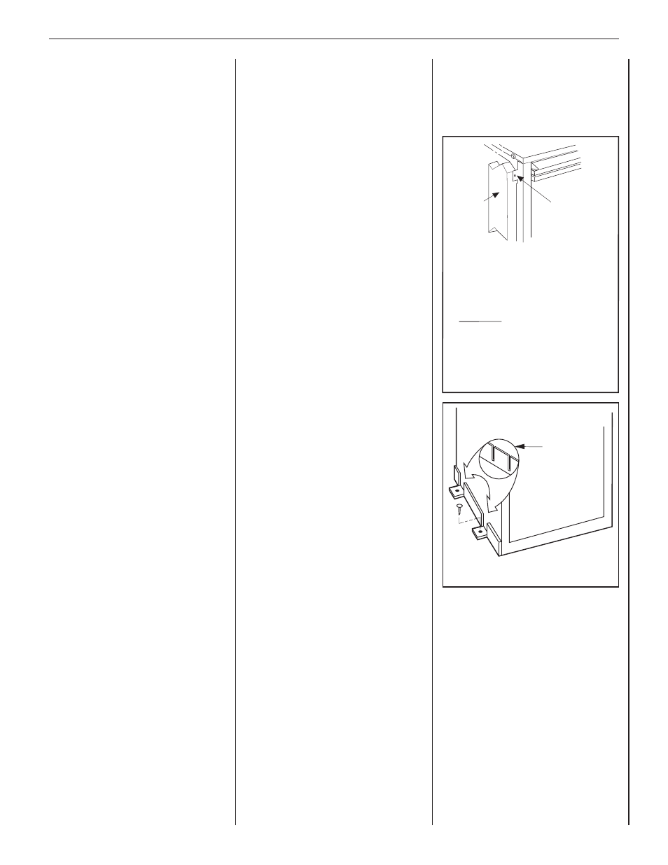
Secure the fi replace to the side framing
members using the unit’s nailing fl anges
— one top and bottom on each side of the
fi replace front (See Figure 7). Use 8d nails or
their equivalent.
TYPICAL INSTALLATION SEQUENCE
The typical sequence of installation is
outlined below; however, each installation
is unique and may result in variations to the
steps described. See the pages referenced in
the following steps for detailed procedures.
Step 1. FRAMING (Page 7): Construct the
appliance framing. Position the appliance
within the framing and secure with nailing
nailing fl anges and fl oor anchor tabs.
Bend out the appropriate nailing fl anges for
the drywall/fi nish material to be used. Nailing
fl anges are provided for fl ush framing, 1/2 in.
and 5/8 in. framing depths (see Figure 10).
Step 2. ROUTING GAS LINE (Page 9): Route
gas supply line to appliance location.
Step 3. INSTALLING VENT SYSTEM
(Page 10): Install the vent system and
exterior termination.
Step 4. FIELD WIRING (Page 11).
a. Millivolt Appliances—Install the operating
control switch (not factory provided). If
installing the optional forced air circulating
blower, bring in electrical service line.
b. Electronic Appliances—Field wire and
install operating control switch.
Step 5. WIRING—OPTIONAL FORCED AIR
BLOWER KIT (Page 12).
Step 6. CONNECTING GAS LINE (Page 12):
Make connection to gas supply.
Step 7. INSTALLING OPTIONAL OUTSIDE
AIR KIT (Page 13)
Step 8. VERIFYING APPLIANCE OPERATION
(Page 14).
FLOOR NAILING TABS
Fireplace may be anchored to fl oor. Bend
down two anchor tabs (one on each side)
located at the base of the fi replace and
secure to the fl oor by nailing with 8d nails or
equivalent (see Figure 8).
Anchor
Tab
Figure 8: Floor Anchor Tabs
Step 9. INSTALLING VOLCANIC STONE,
GLOWING EMBERS, AND LOGS (Page 14).
Step 10. REMOVING AND INSTALLING THE
GLASS DOOR (Page 19).
Step 11. BURNER ADJUSTMENTS (Page 19):
Adjust burner primary air shutter to achieve
proper fl ame appearance.
Step 12. TESTING VENT OPERATION
(Page 21)
Vent operation test and (safety limit) switch
operation.
Step 13. HOOD INSTALLATION (Page 21).
Step 14. FINISHING REQUIREMENTS (Page 21)
Step 15. ATTACHING SAFETY-IN-
OPERATION WARNINGS (Page 21).
DETAILED INSTALLATION STEPS
STEP 1. FRAMING
Frame the appliance as illustrated in Figure 9
on Page 8. All framing details must allow for
a minimum clearance to combustible framing
members as shown in the table on Page 8.
If the appliance is to be elevated above fl oor
level, a solid continuous platform must be
constructed below the appliance.
Note: The framed depth, 16 in. (406 mm) from
a framed wall, must always be measured from
a fi nished surface. If a wall covering such as
drywall is to be attached to the rear wall, then
the 16 in. (406 mm) must be measured from
the drywall surface. It is important that this
dimension be exact.
Note: Some units only have one anchor tab
on each side.
Figure 7: Unit Secured to Framing by
Nailing Flange
Note: The nailing flanges, combustible members
and screw heads located in areas directly adjacent
to the nailing flanges, are EXEMPT from the 1/2”
clearance to combustible requirements for the
firebox outer wrapper. Combustible framing may be
in direct contact with the nailing flanges and may
be located closer than 1/2” from screw heads and
the firebox wrapper in areas adjacent to the nailing
flanges. Frame the opening to the exact dimensions
specified in the framing details of this manual.
Side
Framing
Unit Nailing Flange
(No clearance to
combustible
framing is required)
Left Side Front Corner of Fireplace Shown
(Right Side Requirements the Same)