Lennox International Inc. MERIT PLUS MPB3530CNM-B User Manual
Page 21
21
NOTE: DIAGRAMS & ILLUSTRATIONS ARE NOT TO SCALE.
LENNOX HEARTH PRODUCTS • MERIT PLUS
®
B-VENT GAS FIREPLACES (MPB33/35/40/45) • INSTALLATION INSTRUCTIONS
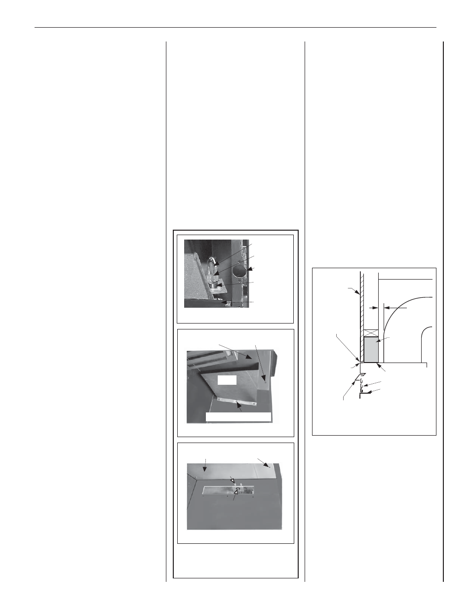
Figure 35: Louver Face Models
Combustible
Finished Wall
Materials
Min. 1 in.
(25 mm)
This area must remain
clear of combustible
materials.
Combustible
material may
touch top of
appliance.
Combustible
materials
NOT allowed
below this point
on face
of appliance.
Header
Spacing
Top Standoff
Top of Appliance
Top of Door Frame
Hood must be installed as shown.
Louvers
STEP 13. HOOD INSTALLATION
Refer to Figure 35. All models must have
hoods installed prior to operating.
On louvered face units, slide the hood into the
slots on the lower edge of the cabinet top above
the louvered vent (see Figure 35).
STEP 14. FINISHING REQUIREMENTS
Wall Details
Complete fi nished interior wall. To install the
appliance facing fl ush with the fi nished wall,
position framework to accommodate the
thickness of the fi nished wall (see Figure 9
on Page 8).
See Page 4 for
Cold Climate Insulation and
Page 8 for Clearances.
STEP 12. TESTING VENT OPERATION
After appliance installation, perform this vent
operation test to verify that proper venting
conditions exist:
1. Place unit in its normally-operated
condition, that is, with the glass
enclosure panel in place.
2. Close all doors and windows in the room.
Turn on all exhaust fans in the house.
3. Light the appliance.
4. Wait 15 minutes.
5. To check for venting action, start by
holding a smoke producing device
below the glass enclosure panel.
The smoke should be drawn into the
control compartment. Continue the
test by moving the smoke producing
device along the entire length of
below the glass door.
6. If the smoke is not drawn into the
control compartment, turn off the
appliance and call a qualified service
technician.
RESETTING THE SAFETY LIMIT SWITCH
This appliance is equipped with a manually
resetable safety limit switch. Refer to
Figure 34 for its location. If, during appliance
operation, the flame goes out (independently
of the burner on/off wall switch), it may
be due to a blocked vent. If this condition
occurs, the safety limit switch will activate,
causing the fireplace burner to shut off. To
reset this switch, first allow the appliance
to cool, then remove the top louver panel.
Reset the safety limit switch by pushing the
red reset button, located between the wire
terminals on the back of the switch (See
Figure 34, Detail A).
The appliance should then relight and remain lit.
Reinstall the top louver panel. If the appliance
does not relight, turn off the appliance and call
for a qualified service technician.
To replace the blocked flue safety limit switch
(see
Figure 34, Details B & C).
This procedure should only be performed by a
qualified service technician.
IMPORTANT - TURN ELECTRICAL POWER
OFF BEFORE BEGINNING THIS PROCEDURE.
1. Lower the bottom control
compartment access panel.
Remove the glass enclosure panel:
open the latch (located in the center
of the unit front opening, under the
fi rebox fl oor) securing the glass
enclosure panel. Remove the panel
by tilting it outward at the bottom
and lifting it up. Set the door aside
protecting it from inadvertent
damage (see Figure 29 on Page 19).
2. Remove the lintel securing screws
(3) and then remove the lintel. One
of the lintel cabinet top holes is
shown in Figure 34, Detail B.
Scoop
Scoop Securing Screws
Firebox Top
Lintel Securing Screw
Hole in Cabinet Top
Figure 34: Safety Limit Switch
Blocked Flue Safety Limit Switch Location, Inside
View of Firebox, Top/Right Side Intersection
Detail A
Firebox Top
Limit Switch
Limit Switch/Bracket
Securing Screws
Lintel Securing-Screw
Hole in Cabinet Top
View Without Scoop
Detail C
3. Remove the scoop securing screws
(3) and then remove the scoop (see
Figure 34, Detail B).
4. Remove the safety switch bracket
securing screws (2), and pull the
switch/bracket assembly, with low
voltage wires attached, through the
side panel slot into the fi rebox (see
Figure 34, Detail C).
5. Replace the switch.
6. Reinstall the switch/bracket
assembly.
7. Reinstall the scoop and lintel.
8. Reinstall the glass enclosure panel.
9. Raise the bottom control
compartment access panel.
10. The appliance should then relight
and remain lit. If this does not
occur, check unit for a blocked fl ue
condition.
Detail B
Wire
Terminals
Back Of
Limit
Switch
Cabinet
Corner
Door
Frame
Reset Button