Warning, Caution – Lennox International Inc. MERIT PLUS MPB3530CNM-B User Manual
Page 13
13
NOTE: DIAGRAMS & ILLUSTRATIONS ARE NOT TO SCALE.
LENNOX HEARTH PRODUCTS • MERIT PLUS
®
B-VENT GAS FIREPLACES (MPB33/35/40/45) • INSTALLATION INSTRUCTIONS
Operate the actuator through several
cycles including the closed position.
Ensuring proper operation and freedom of
movement. Return the actuator arm to the
closed position.
Note: Do not terminate an outside air kit in the
attic space under any circumstances.
After completing the installation of the
optional outside air vent system the outside
air control lever must be put in service and
tested to ensure proper operation before
completing any enclosure around the fi rebox.
Failure to do so may result in extensive and
costly rework. Before the operation of the
vent system can be tested, the lever securing
screw must be removed (see Figure 20).
The hand operated outside air control lever
is located on the left side of the fi replace
opening (see Figure 20).
STEP 7. INSTALLING OUTSIDE AIR KIT
Optional outside make-up air kits, Model
FOAK-4 or FAOK-4LD (see Figure 21 on Page
14), may be used with these appliances.
Refer to the installation instructions packaged
with the air kits for specifi c installation
information. If used, the outside air kit must
be installed before the fi replace is framed and
enclosed in the fi nished wall.
Outside air drawn into the fi replace supplies
air to the fi re for combustion. Only one
outside air duct is necessary, if installed. See
Figure 3 on Page 5 for the location of the
unit's outside air inlet.
If additional length of duct is necessary,
purchase locally available U.L. Class 0
or Class 1 metallic ducting. The duct may
extend up to 50' (15.24 m) in any direction.
Note: When installing the air duct vertically, DO
NOT terminate the duct closer than 3' below
the chimney top.
Outside supplemental combustion air ducting
may be run upwards or vertically through
framing and ceiling joists, with the hood
installed through an outside wall and 3' (1 m)
below the termination. Ducting may also
be run downward through fl oor joists and
under the home to a ventilated crawlspace
not considered part of the living area of the
home.
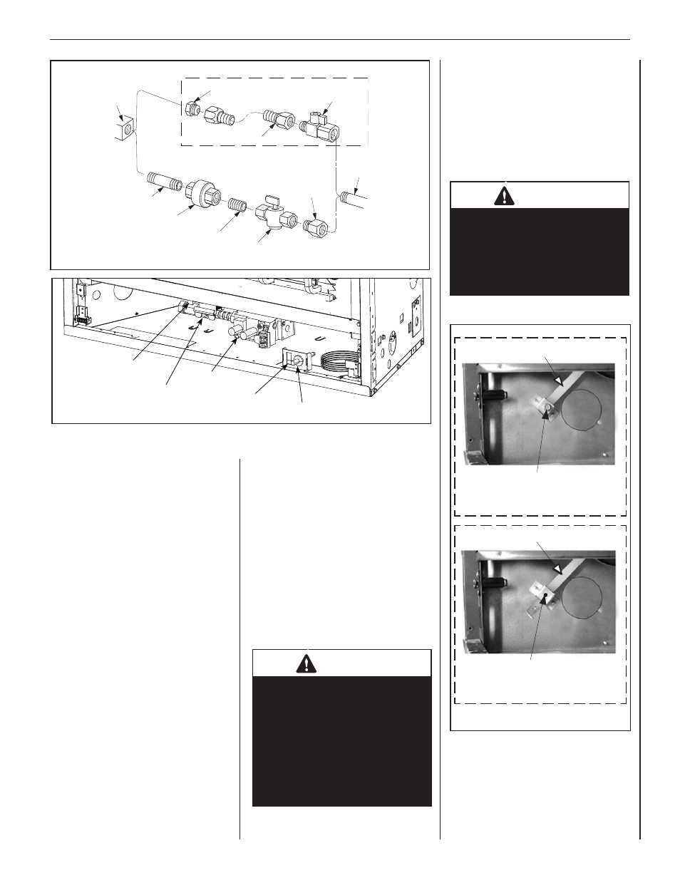
Outside Air Control Lever
Outside Air Control Lever
Securing screw
Air Shutter in Closed Position
Outside Air Control Lever
Outside Air Control Lever
Securing Screw Removed
Air Shutter in Open Position
Figure 20: Outside Air Control Lever
WARNING
DO NOT operate the outside
air control lever with a fi re in
the fi rebox unless a complete
outside combustion air vent
system has been installed with
the appliance.
CAUTION
Never locate inlet where it can be
blocked by shrubs, snow drifts,
etc. Never locate inlet in garage
or any area where there is another
fuel burning appliance or products
emitting combustible gases such
as paint, gasoline, etc. In cold
climates, it is recommended the
outside air duct be insulated.
To open the outside air shutter, open the
bottom control access panel, reach into the
control compartment, and pull the outside
air control lever all the way out. The outside
air shutter should be fully open when the
fi replace is in use and completely closed
when the fi replace is not being used. Closing
it when not in use will prevent outside cold
air from entering the dwelling.
Figure 18: Gas Connection
Gas
Stub
1/2" x 3/8" Flare
Shut-Off Valve
3/8" Flex Tubing
3/8" NPT x 3/8"
Flare Fitting
3/8" Nipple
3/8" Union
3/8" Close Nipple
3/8" Shut-Off Valve
1/2" x 3/8"
Reducer
Gas
Valve
Optional Gas Flex Line Connector
Piezo
(Optional) Burner
ON/OFF Switch
Main Gas
Shut-Off Valve
Gas Valve
B-Vent Units Have
A Single Door Latch
Figure 19: Millivolt Gas Valve—Lower Control Compartment