Lennox International Inc. MERIT PLUS MPB3530CNM-B User Manual
Page 4
4
NOTE: DIAGRAMS & ILLUSTRATIONS ARE NOT TO SCALE.
LENNOX HEARTH PRODUCTS • MERIT PLUS
®
B-VENT GAS FIREPLACES (MPB33/35/40/45) • INSTALLATION INSTRUCTIONS
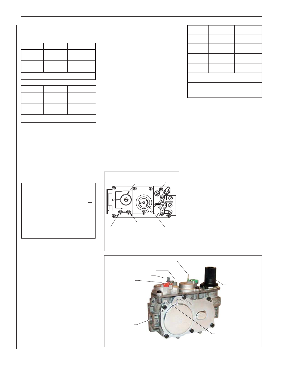
Test gauge connections are provided on
the front of the millivolt and electronic gas
control valve (identifi ed IN for the inlet and
OUT for the manifold side). The control
valves have a 3/8 in. (10 mm) NPT thread
inlet and outlet side of the valve (refer to
Figures 1 and 2).
Propane tanks are at pressures that will
cause damage to valve components. Verify
that the tanks have step down regulators to
reduce the pressure to safe levels.
ORIFICE SIZES—SEA LEVEL TO HIGH
ALTITUDE (ALL MODELS)
These appliances are tested and approved
for installation at elevations of 0–4500 ft
(0–1372 m) above sea level using the
standard burner orifi ce sizes (marked with an
"*" in Table 4). For elevations above 4500 ft,
contact your gas supplier or qualifi ed service
technician.
Deration—At higher elevations, the amount
of BTU fuel value delivered must be reduced
by either:
• Using gas that has been derated by the
gas company.
• Changing the burner orifi ce to a smaller
size as regulated by the local authorities
having jurisdiction and by the (USA)
National Fuel Gas Code NFPA 54—latest
edition / ANSI Z223.1 or, in Canada, the
CAN/CGA-B149.1 codes—latest edition.
Fuel #
Low
High
Natural Gas
1.6 in. WC
(0.40 kPa)
3.5 in. WC
(0.87 kPa)
Propane
6.3 in. WC
(1.57 kPa)
10.0 in. WC
(2.49 kPa)
Table 3: Manifold Gas Supply Pressure
The appliance and its appliance main gas
valve must be disconnected from the gas
supply piping system during any pressure
testing of that system at test pressures in
excess of 1/2 psi (3.5 kPa).
The appliance must be isolated from
the gas supply piping system by closing
its equipment shutoff valve during any
pressure testing of the gas supply piping
system at test pressures equal to or less
than 1/2 psi (3.5 kPa).
Install the appliance according to the
regulations of the local authorities having
jurisdiction and, in the USA, the National Fuel
Gas Code NFPA 54—latest edition / ANSI
Z223.1 or, in Canada, the CAN/CGA-B149.1—
latest edition.
Flame breadth, height and width will diminish
4% for every 1,000 feet of altitude. Gas Valve
Diagrams
.
See Figure 1 for millivolt models
and Figure 2 For electronic models.
In Canada - CAN/CGA-2.17-M91 (R2009)
(high altitude): THE CONVERSION SHALL
BE CARRIED OUT BY A MANUFACTURER’S
AUTHORIZED REPRESENTATIVE, IN
ACCORDANCE WITH THE REQUIREMENTS
OF THE MANUFACTURER, PROVINCIAL
OR TERRITORIAL AUTHORITIES HAVING
JURISDICTION AND IN ACCORDANCE
WITH THE REQUIREMENTS OF THE
CAN/CGA-B149.1 OR CAN/CGA-B149.2
INSTALLATION CODES.
REQUIREMENTS FOR THE
COMMONWEALTH OF MASSACHUSETTS
These fi replaces are approved for installation
in the US state of Massachusetts if the
following additional requirements are met:
• Install this appliance in accordance with
Massachusetts Rules and Regulations
248 C.M.R.
• Installation and repair must be done by
a plumber or gas fi tter licensed in the
Commonwealth of Massachusetts.
• The fl exible gas line connector used shall
not exceed 36 in. (92 cm) in length.
• The individual manual shut-off must be a
T-handle type valve.
COLD CLIMATE INSULATION
For cold climate installations, seal all cracks
around your appliance with noncombustible
material and wherever cold air could enter the
room. It is especially important to insulate
outside chase cavity between studs and
under fl oor on which appliance rests, if fl oor
is above ground level. Gas line holes and
other openings should be caulked or stuffed
with unfaced fi berglass insulation.
If the fi replace is being installed on a
cement slab in cold climates, a sheet of
plywood or other raised platform can be
placed underneath to prevent conduction
of cold transferring to the fi replace and into
the room. It also helps to sheetrock inside
surfaces and tape for maximum air tightness
and caulk fi restops.
MANUFACTURED HOUSING
B-Vent Fireplaces are not approved for use in
OEM or aftermarket manufactured housing
built to HUD standards.
Fuel #
Minimum
Maximum
Natural Gas
4.5 in. WC
(1.12 kPa)
10.5 in. WC
(2.61 kPa)
Propane
11.0 in. WC
(2.74 kPa)
13.0 in. WC
(3.23 kPa)
Table 2: Inlet Gas Supply Pressure
GAS PRESSURE—ALL MODELS
Tables 2 and 3 show the appliances' inlet and
manifold gas pressure requirements:
H I
LO
W
HT
PT
HT
PT
PI
LOT
PI
L
O
T
ON
it
OFF
IN
OUT
HI/LO Variable
Flame Height
Adjustment
Figure 1: SIT Millivolt Gas Valve
Manifold Pressure Tap
Inlet Pressure Tap
Pilot Adjustment
Screw
Main Gas Control Knob
OFF/PILOT/ON
Orange Wire
(from DFC Wire
Harness)
Main Gas Inlet
3/8 in. NPT
Green Wire
(from DFC Wire Harness)
Inlet (IN) Test Port
Manifold (OUT) Test Port
Figure 2: SIT Electronic Gas Valve
Hi/Lo Flame
Control Knob
Yellow Ground Wire
(from DFC Wire Harness)
Model
Series
Nat.Gas
drill size (inches)
Propane
drill size (inches)
MPB33
#47 (.0785") *
99K74 •
(.048")*
99K78 •
MPB35
#44 (.086") *
60J80 •
#55 (.052") *
19L52 •
MPB40
#38 (.102") *
99K76 •
(.0625") *
21L01 •
MPB45
#36 (.104") *
24M10 •
#52 (.0635") *
37G00 •
* Standard size installed at factory
• Part /Cat. Number
Table 4: Burner Orifi ce Sizes
Elevation 0-4500 feet
(0-1372 meters)