Warning – Lennox International Inc. MERIT PLUS MPB3530CNM-B User Manual
Page 14
14
NOTE: DIAGRAMS & ILLUSTRATIONS ARE NOT TO SCALE.
LENNOX HEARTH PRODUCTS • MERIT PLUS
®
B-VENT GAS FIREPLACES (MPB33/35/40/45) • INSTALLATION INSTRUCTIONS
Outside Combustion Air Kits
Cat. No.
Model No.
Description
81L87
FOAK-4
Combustion Air Kit (w/duct)
81L88
FOAK-4LD
Combustion Air Kit (w/o duct)
Figure 21: Outside Combustion Air Kits
WARNING
• DO NOT attempt to install the
logs until the appliance installa-
tion has been completed, the gas
line connected and tested for leaks
and the initial burner operation
has been checked out.
•
The size and position of the log set
was engineered to give the appli-
ance a safe, reliable and attractive
fl ame pattern. Any attempt to use
a different log set in the fi replace
will void the warranty and will
result in incomplete combustion,
sooting, and poor fl ame quality.
•
Logs get very hot and will remain
hot up to one hour after gas supply
is turned off. Handle only when logs
are cool. Turn off all electricity to the
appliance before you install grate,
volcanic stone, embers and logs.
•
This appliance is not designed to
burn wood. Any attempt to do so
could cause irreparable damage to
the appliance and prove hazardous
to your safety.
•
If logs are not installed accord-
ing to the log installation instruc-
tions, fl ame impingement and
improper combustion could
occur and result in soot and/or
excessive production of carbon
monoxide (CO), a colorless,
odorless, toxic gas.
STEP 9. INSTALLING VOLCANIC
STONE, GLOWING EMBERS, AND LOGS
Locate the packaged carton of logs (which
were located in the fi rebox). The decorative
volcanic stone and glowing embers were
packaged separately in plastic bags located
in the control area of the fi replace.
DO NOT attempt to install the logs until the
appliance installation has been completed,
the gas line connected and tested for leaks,
and the initial burner operation has been
checked out.
Proper log placement is critical to encourage
outstanding fl ame appearance and prevent
sooting. When positioned properly as shown,
logs will be positioned between fl ame peaks
and will not impinge any fl ames.
Refer to Figure 26 for MPB33 Series
appliances, Figure 27 for MPB35 Series
appliances and Figure 28 for MPB40 and
MPB45 Series appliances.
NOTE: Turn off all electricity to the appliance
before you install volcanic stone, embers
and logs.
ELECTRONIC APPLIANCE CHECKOUT
To light the burner, turn ‘ON’ the wall or
remote control switch. Ensure the igniter
lights the pilot. The pilot fl ame should engulf
the fl ame rod as shown in Figure 23.
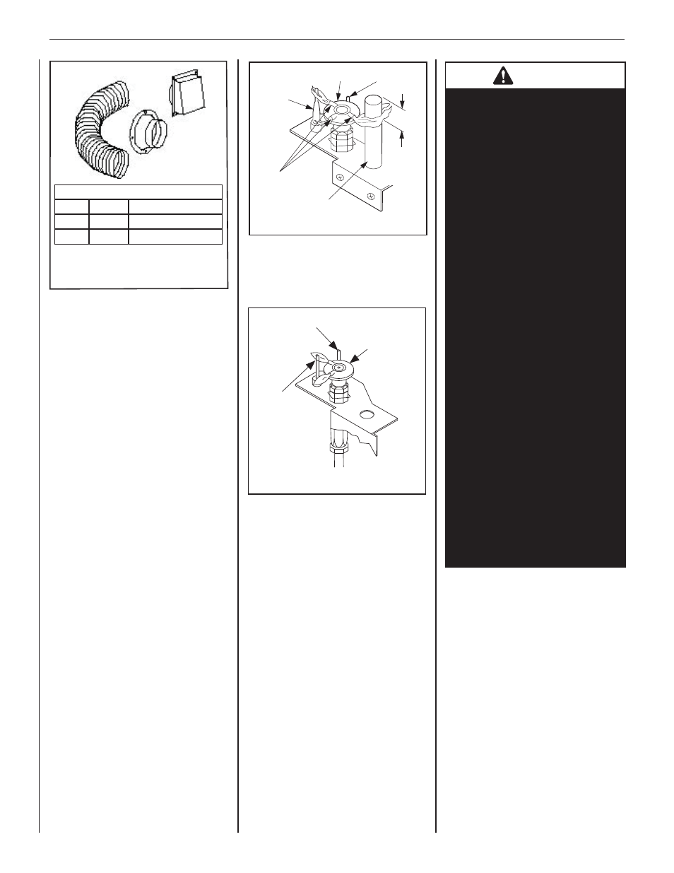
MILLIVOLT APPLIANCE CHECKOUT
The pilot fl ame should be steady, not lifting
or fl oating. Flame should be blue in color
with traces of orange at the outer edge.
The top 3/8 in. (10 mm) at the pilot generator
(thermopile) and the top 1/8 in. minimum
(tip) of the quick drop out thermocouple
should be engulfed in the pilot fl ame.
The fl ame should project 1 in. (25 mm)
beyond the hood at all three ports (see
Figure 22). Replace logs if removed for pilot
inspection.
To light the burner; turn “ON” the remote wall
switch and rotate the gas valve control knob
counterclockwise to the “ON” position (“ON”
will be at the top side of the valve).
Pilot
Hood
Sensor
Igniter
Flame Rod
(sensor)
Figure 23: Electronic Pilot
STEP 8. VERIFYING APPLIANCE
OPERATION
With gas line installed, run initial system checkout
before closing up the front of the unit. Follow the
pilot lighting instructions provided in the Care and
Operation Instructions. For piezo igniter location
on millivolt appliances, (see Figure 19).
Note: Lighting Instructions are also found on the
literature tag tied to the gas piping next to the gas
valve. To access the tag, open the lower control
compartment door (see Figure 19). To open the
control compartment access panel, actuate the spring
loaded magnetic catches securing the panel. First,
gently depress the upper right top corner of the panel
until the magnet catch "pops" the door free. Then,
gently pulling the panel forward, disengage the left
magnet catch and allow the panel to swing down
to open. When fi rst lighting the appliance, it will
take a few minutes for the line to purge itself of
air. Once purging is complete, the pilot and burner
will light and operate as indicated in the instruction
manual. Subsequent lighting of the appliance will
not require such purging. Inspect the pilot fl ame
(remove logs, if necessary, handling carefully).
Thermocouple
Hood
Igniter Rod
Thermopile
Pilot
Nozzels
3/8 in.
(9 mm)
Min
Figure 22: Millivolt Pilot