Warning, Caution – Lennox International Inc. MERIT PLUS MPB3530CNM-B User Manual
Page 20
20
NOTE: DIAGRAMS & ILLUSTRATIONS ARE NOT TO SCALE.
LENNOX HEARTH PRODUCTS • MERIT PLUS
®
B-VENT GAS FIREPLACES (MPB33/35/40/45) • INSTALLATION INSTRUCTIONS
WARNING
•
Air shutter adjustment should
only be performed by a
qualifi ed professional service
technician.
•
Ensure the front glass panel
is in place and sealed during
adjustment.
CAUTION
•
Soot will be produced if the
air shutter is closed too much.
Any damage due to sooting,
resulting from improperly
setting the air shutter, is not
covered under the warranty.
•
The air shutter door and
nearby appliance surfaces
are hot. Exercise caution to
avoid injury while adjusting
fl ame appearance.
Adjustment Rod Up
(minimum air
opening position)
Air Shutter
Burner Tube
Adjusting Set Screw
Adjustment Rod Down
(fully open position)
Table 8: Air Shutter Opening Setting
Main Burner Factory Air Shutter
Opening Setting - Inches (millimeter)
Model
Natural Gas
Propane Gas
MPB33
Fully Closed
3/16" (4.76 mm)
MPB35
Fully Closed
3/16" (4.76 mm)
MPB40
Fully Closed
3/16" (4.76 mm)
MPB45
Fully Closed
3/16" (4.76 mm)
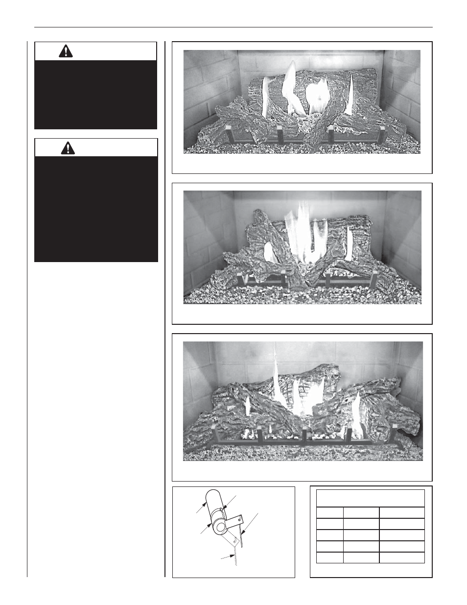
1. Refer to Figures 30, 31, and 32 for
proper fl ame appearance. To adjust the
fl ame, move the rod up and down (the
adjustment rod is located in the lower
control area). Position the air shutter to
the factory setting as shown in Table 8.
2. Light appliance (follow lighting procedure
on lighting label in control compartment
or in the Care and Operation
Instructions).
3. Allow the burner to operate for at least
15 minutes while observing the fl ame
continuously to ensure that the proper
fl ame appearance has been achieved.
If the following conditions are present,
adjust accordingly.
•
If
fl ame appears weak or sooty, adjust
the air shutter, incrementally, to a
more open position until the proper
fl ame appearance is achieved.
• If fl ame remains blue, adjust the air
shutter, incrementally, to a more
closed position until the proper fl ame
appearance is achieved.
4. When satisfi ed that the burner fl ame appear-
ance is normal, reinstall the lower control
compartment door, then proceed to fi nish
the installation.
Figure 30: MPB33 MODEL
Figure 31: MPB35 MODEL
Figure 32: MPB40 AND MPB45 MODEL
Figure 33: Air Shutter