Serial interface, Figure 3-2. front panel layout, Table 3-1. rj45 serial connector pinouts – Lantronix 900-422 User Manual
Page 18: Dr+. (see
3: Installation and Hardware
XPress DR+ User Guide
18
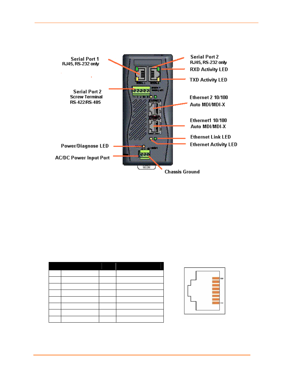
Figure 3-2. Front Panel Layout
Serial Interface
The XPress-DR+ supports RS-232 via RJ45 connectors. It also supports RS-422/485 via
screw terminals (Serial Port 2 only).
Note:
Serial Port 2 supports
RS232, RS422, and RS485, but only one mode at a
time. This means you can use either the RJ45 connector or the terminal block,
not both.
The serial RJ45 serial connectors support RS232, up to 230400 bits per second.
Table 3-1. RJ45
Serial Connector Pinouts
Pin Direction
Name
Function
1
Output from DR+ RTS
Ready To Send
2
Output from DR+ DTR
Data Terminal Ready
3
Output from DR+ TXD
Transmitted Data
4 Ground
GND Signal
Ground
5 Ground
GND Signal
Ground
6
Input to DR+
RXD
Received Data
7
Input to DR+
DSR
Data Carrier Detected
8
Input to DR+
CTS
Clear To Send
Figure 3-3. RJ45 Connector – Front View