Troubleshooting & repair, Caution, Control board removal and replacement (continued) – Lincoln Electric POWER WAVE 355/405 SVM159-A User Manual
Page 91
Observe static precautions detailed in PC
Board Troubleshooting Procedures at the
beginning of this section.
6. Using a phillips head screwdriver remove the two
screws and their washers from above and below
the input power switch. See Figure F.18.
7. Using a phillips head screwdriver remove the four
screws from around the two welder output termi-
nals on the front of the machine. See Figure F.18.
8. The front of the machine may now gently be pulled
forward to gain access to the Control Board.
Note: The front of the machine cannot be removed
completely, only pulled forward a few inches.
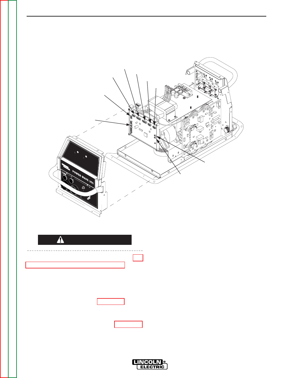
9. Beginning at the right side of the control board
remove plugs J10A and J10B. Note: Be sure to
label each plugs position upon removal. See
Figure F.19.
10. Working your way across the top of the board
from right to left, label and remove plugs #J9, #J8,
#J7, #J6, and #J5. See Figure F.19.
11. Working your way down the left side of the board,
label and remove plugs #J4 and #J2. See Figure
F.19.
CAUTION
POWER WAVE 355/405
TROUBLESHOOTING & REPAIR
F-49
F-49
W
AR
NIN
G
RE
M
OT
E
PO
W
ER
OF
F
ON
STATU
S
TH
ERMAL
LINCOLN
ELECTRIC
J2
J4
J5
J6
J7
J8
J9
J10A
J10B
FIGURE F.19 - CONTROL BOARD ALL PLUG LOCATIONS
CONTROL BOARD REMOVAL AND REPLACEMENT (continued)