Theory of operation, Output rectifier and choke – Lincoln Electric POWER WAVE 355/405 SVM159-A User Manual
Page 39
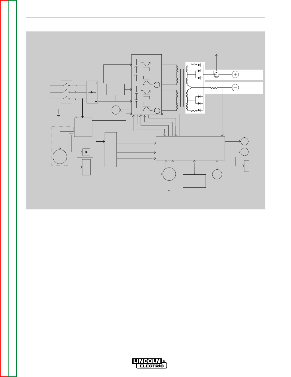
OUTPUT RECTIFIER AND CHOKE
The output rectifier receives the AC output from the
main transformer secondary and rectifies it to a DC
voltage level. Since the output choke is in series with
the negative leg of the output rectifier and also in
series with the welding load, a filtered DC output is
applied to the machine’s output terminals.
THEORY OF OPERATION
E-5
E-5
POWER WAVE 355/405
FIGURE E.5 – OUTPUT RECTIFIER AND CHOKE
Control Board
Choke
Positive
Output
Terminal
Negative
Output
Terminal
To Control
Board
Current
Feedback
Reconnect
Switch
Output V
oltage Sense
Input switch
Input
Rectifier
Auxiliary
Transformer
Fan
Power
Board
220
Receptacle
RS232 Supply +5VDC
Machine Control Supply
+15VDC, -15VDC, +5VDC
40VDC
42VAC
220 VAC
Main Switch Board
115VAC Fan Supply
Fan Control
V/F Capacitor Feedback (2)
Soft Start Control
Input Relay Control
Primary Current Feedback(2)
IGBT
Drive S
ignal
Primary
Current
Sensor
Primary
Current
Sensor
{
P
o
w
e
r
W
a
v
e
4
0
5
o
n
l
y
65V
AC
DC
Bus
Board
Wire
Feeder
Recp.
40VDC
Can Supply +5VDC
Arc
Link
Electrode
Sense
21 Lead
Voltage
Sense
Recp.
R232
Connector
Yellow
Thermal
LED
Status
Red/Green
LED
Thermostats
2
To
Feeder
NOTE: Unshaded areas of Block Logic Diagram are the subject of discussion.