Electrical characteristics, Table 32. usb transceiver driver characteristics, Table 33 . capacitance values – Lucent Technologies USS-720 User Manual
Page 52: Instant usb, Ieee
5-26
Lucent Technologies Inc.
USS-720
Instant USB
Preliminary Data Sheet, Rev. 5
USB-to-
IEEE
1284 Bridge
September 1999
13
Electrical Characteristics
Table 31. dc Characteristics (T
A
= 0
°
C to 70
°
C, V
DD
= 3.3 V
±
0.3 V, V
SS
= 0 V.)
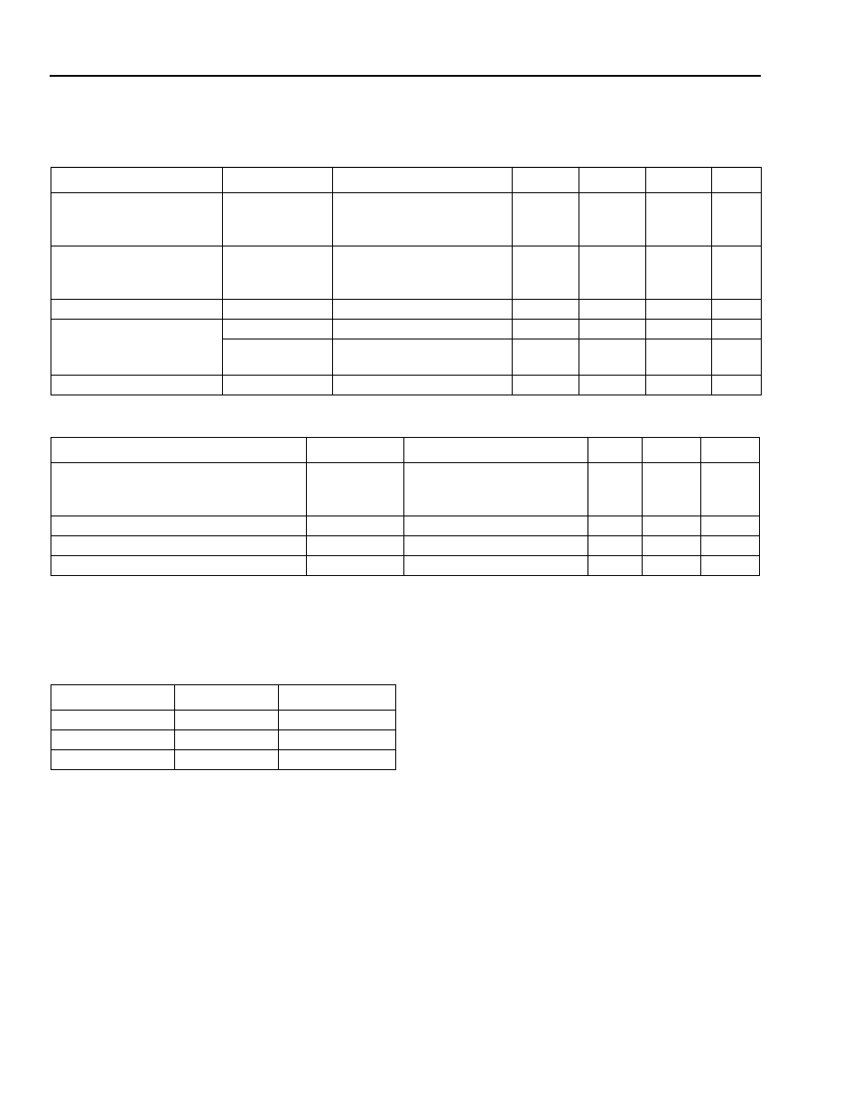
Table 32. USB Transceiver Driver Characteristics
* The output impedance includes both the external resistor and the transceiver.
The USS-720 is a 3.3 V part, and it has separate pins (V
DD
5) for power to the
IEEE 1284 drivers. Capacitance val-
ues for the USS-720 pins are listed in Table 33.
Parameter
Symbol
Test Conditions
Min
Typ
Max
Unit
Input Voltage:
Low
High
V
IL
V
IH
—
—
—
2.0
—
—
0.8
—
V
V
Output Voltage:
Low
High
V
OL
V
OH
—
—
—
2.4
—
—
0.4
—
V
V
Power Dissipation
P
D
25
°
C, V
DD
= 3.3 V
1.65
231
323.4
mW
Power Supply Voltage
V
DD,
V
DDA
—
3
3.3
3.6
V
V
DD5
5 V environment
3 V environment
4.375
3
5
3.3
5.5
3.6
V
V
Power Supply Current
I
DD
—
0.5
70
98
mA
Parameter
Symbol
Test Conditions
Min
Max
Unit
Rise and Fall Times:
(10%—90%)
(90%—10%)
t
R
t
F
OEN = 0, C
L
= 50 pF
4
4
20
20
ns
ns
Rise/Fall Time Matching
t
RFM
OEN = 0, C
L
= 50 pF
90
110
%
Crossover Point
V
CRS
OEN = 0, C
L
= 50 pF
1.3
2.0
V
Output Impedance*
Z
DRV
OEN = 0
28
43
Ω
Table 33. Capacitance Values
Parameter
Value
Unit
CLK_LO
1.0
pF
CLK_HI
1.0
pF
All Other Pins
3.0
pF