External circuitry requirements, Figure 3 . external crystal connection, Figure 5 . self-powered device example connection – Lucent Technologies USS-720 User Manual
Page 50: Figure 6 . uss-720 connection to ieee 1284, Instant usb, Ieee, Uss-720, Preliminary data sheet, rev. 5 usb-to
5-24
Lucent Technologies Inc.
USS-720
Instant USB
Preliminary Data Sheet, Rev. 5
USB-to-
IEEE
1284 Bridge
September 1999
13
External Circuitry Requirements
The USS-720 is intended to be a single-chip solution.
As such, the USB transceiver and the
IEEE 1284 buff-
ers have been integrated on-chip. External require-
ments include a 3.3 V supply and a 1.5 k
Ω ±
5% pull-up
resistor for the DPLS pin. If the internal oscillator is
used, a 12 MHz crystal along with bias capacitors are
needed (see Figure 3). If the internal oscillator is not
used, a 12 MHz clock signal should be supplied to
CLK_LO, and CLK_HI should be left unconnected.
1.2 k
Ω ±
5% pull-up resistors are needed on all
IEEE
1284 signals (except PLH), unless used in the High
Drive Mode (see the following page). A 5 V supply and
USB and/or
IEEE 1284 connectors might also be
needed, depending on the application.
Figure 3. External Crystal Connection
Figure 4 shows the normal USS-720 connection to the
USB. Both DPLS and DMNS require 24
Ω ±
1% series
resistors for USB impedance matching. Additionally, a
1.5 k
Ω
pull-up resistor is required on DPLS for full-
speed/low-speed differentiation.
Figure 4. USB Transceiver Connection
(Normal Mode)
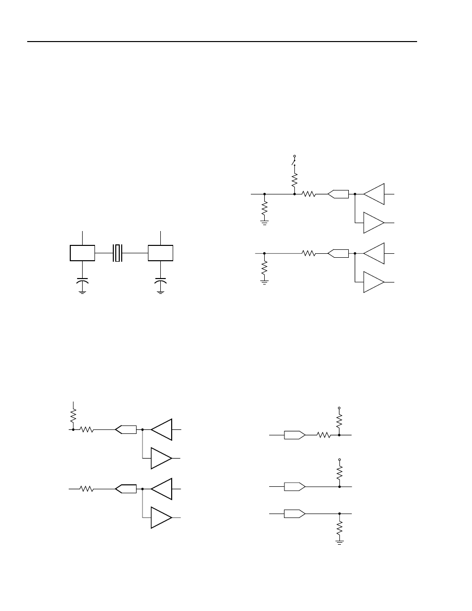
For using the USS-720 in a self-powered device, there
are some additional considerations. The device must
refrain from supplying power through the pull-up
resistor when the device is plugged into an unpowered
bus. The USS-720 device circuit must also ensure that
the DPLS and DMNS lines are in an appropriate state
when the device is powered but not plugged in.
Figure 5 shows an example connection to meet these
requirements.
Figure 5. Self-Powered Device Example Connection
Figure 6 shows a USS-720-to-
IEEE 1284 parallel port
connection that complies with the
IEEE 1284 specifica-
tion. Other connections are also possible. While the
IEEE specification requires these resistors, developers
must make their own design decision against the
500
µ
A suspend mode current requirements required
by the USB specification.
Figure 6. USS-720 Connection to
IEEE 1284
5-5259.r2
CRYSTAL
12 MHz
CLK_LO
15 pF
CLK_HI
15 pF
TO INTERNAL
USS-720
TO INTERNAL
USS-720
5-5404.r1
+3.3 V V
DD
DPLS
DMNS
1.5 k
Ω ±
5%
24
Ω ±
1%
24
Ω ±
1%
5-5506a.r4
DPLS
DMNS
24
Ω ±
1%
24
Ω ±
1%
+3.3 V
1.5 M
Ω
SWITCH ON WHEN V
BUS
IS POWERED
1.5 k
Ω ±
5%
1.5 M
Ω
+5 V
PLH
7.5 k
Ω ±
5%
1.2 k
Ω ±
5%
ALL PARALLEL PORT
INPUT SIGNALS
EXCEPT PLH
+5 V
1.2 k
Ω ±
5%
ALL PARALLEL PORT
OUTPUT SIGNALS
24
Ω ±
5%
5-5505a.r1