Kawasaki Band Saw User Manual
Page 11
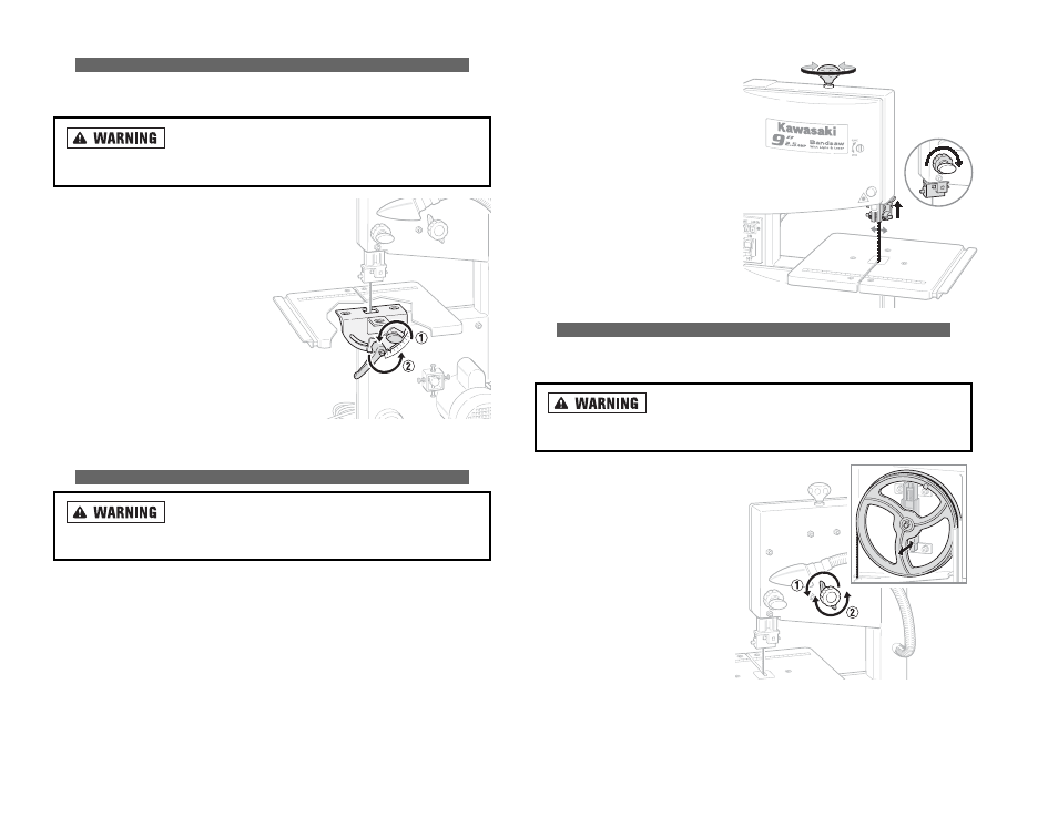
1. To increase blade tension, turn the
blade tension knob clockwise.
2. To reduce blade tension, turn the
blade tension knob counterclock-
wise.
3. Fully raise the upper blade guide.
4. Check the tension by pushing the
side of the blade, halfway between
the table and upper blade guide,
with your finger. The blade should
bend no more than 5/64 to 1/8 inch.
5. Correct the tension as needed by
turning the blade tension knob and
then measuring bending again.
A
AD
DJJU
US
ST
TIIN
NG
G B
BL
LA
AD
DE
E T
TR
RA
AC
CK
KIIN
NG
G
This procedure is followed to ensure that the blade is centered on the band saw
wheels.
A
Allw
waayyss rreem
mo
ovvee p
po
ow
weerr tto
o tth
hee ssaaw
w,, b
byy ttu
urrn
niin
ng
g tth
hee p
po
ow
weerr
ssw
wiittcch
h o
offff aan
nd
d tth
heen
n u
un
np
pllu
ug
gg
giin
ng
g iitt,, b
beeffo
orree m
maakkiin
ng
g aan
nyy aad
djju
ussttm
meen
nttss.. FFaaiillu
urree tto
o
d
do
o sso
o ccaan
n rreessu
ulltt iin
n sseevveerree iin
njju
urryy o
orr d
deeaatth
h..
1. Unlock and open the housing
doors.
2. Loosen the blade tracking locking
nut.
3. While rotating the band saw wheel
by hand, turn the blade tracking
adjustment knob: clockwise if the
blade runs toward the front of the
saw or counterclockwise if the
blade runs toward the back.
4. When tracking properly, tighten the
blade tracking nut.
20
A
AD
DJJU
US
ST
TIIN
NG
G T
TH
HE
E B
BE
EV
VE
EL
L A
AN
NG
GL
LE
E
The bevel adjustment allows material to be cut at any angle between 0 and 45
degrees.
A
Allw
waayyss rreem
mo
ovvee p
po
ow
weerr tto
o tth
hee ssaaw
w b
byy ttu
urrn
niin
ng
g tth
hee p
po
ow
weerr
ssw
wiittcch
h o
offff aan
nd
d tth
heen
n u
un
np
pllu
ug
gg
giin
ng
g iitt,, b
beeffo
orree m
maakkiin
ng
g aan
nyy aad
djju
ussttm
meen
nttss.. FFaaiillu
urree tto
o
d
do
o sso
o ccaan
n rreessu
ulltt iin
n sseevveerree iin
njju
urryy o
orr d
deeaatth
h..
1. Loosen the table locking knob.
NOTE: the table setting lever works on a
cam allowing you to pull it toward you
and back if you run out of room.
2. Loosen the table setting lever.
3. Adjust the bevel adjustment scale
located under the table to help set the
table to the desired angle between 0
and 45 degrees.
4. Tighten the table setting lever and the
table locking knob to secure the table
in position.
5. Make a practice cut on a scrap piece of
similar wood and adjust the table as needed for precision.
A
AD
DJJU
US
ST
TIIN
NG
G S
SA
AW
W B
BL
LA
AD
DE
E T
TE
EN
NS
SIIO
ON
N
A
Allw
waayyss rreem
mo
ovvee p
po
ow
weerr tto
o tth
hee ssaaw
w b
byy ttu
urrn
niin
ng
g tth
hee p
po
ow
weerr
ssw
wiittcch
h o
offff aan
nd
d tth
heen
n u
un
np
pllu
ug
gg
giin
ng
g iitt,, b
beeffo
orree m
maakkiin
ng
g aan
nyy aad
djju
ussttm
meen
nttss.. FFaaiillu
urree tto
o
d
do
o sso
o ccaan
n rreessu
ulltt iin
n sseevveerree iin
njju
urryy o
orr d
deeaatth
h..
19
INCREASE
DECREASE
5/64" TO 1/8"