3 - connecting system components, 3 connecting system components – KVH Industries LF User Manual
Page 16
2-5
Installation
54-0194 Rev. D
2.3
Connecting System Components
The following sections provide instructions for properly wiring
the antenna unit to the components inside the vehicle.
Locating the Switchplate
Before running cables, you need to determine the location for the
TracVision LF/SF switchplate.
1. The switchplate should be installed in a dry, flat
location within reach of the cables that will
connect to the antenna unit.
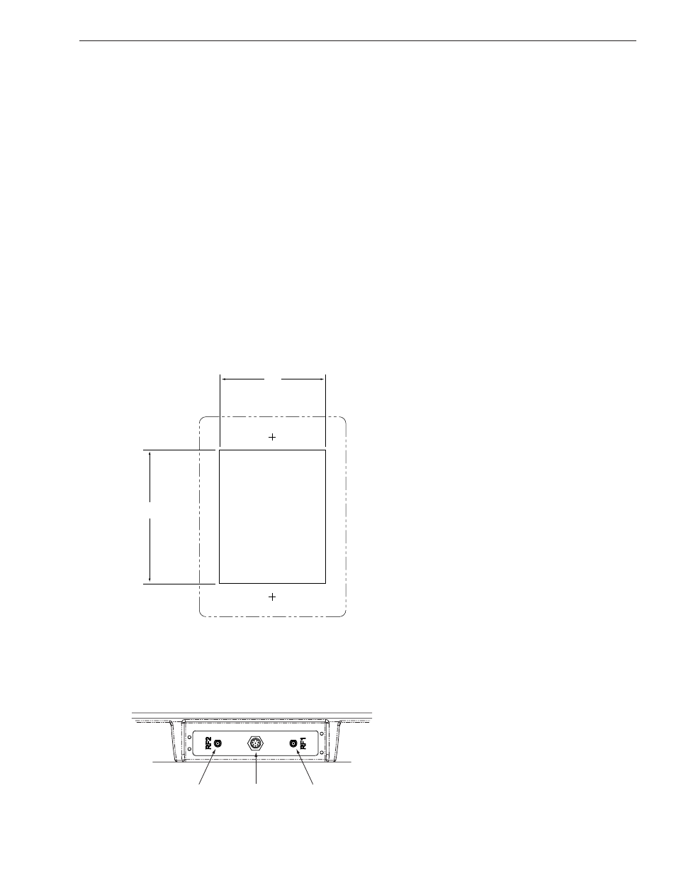
2. Once you’ve decided on a suitable location, create
a panel cutout in the mounting surface. Figure 2-5
illustrates the mounting dimensions and a full-size
template has been provided in Appendix C. All
connecting cables will be routed through this
cutout.
Figure 2-6 shows the antenna unit’s baseplate connectors.
Figure 2-7 on the following page shows the switchplate’s
connectors. Refer to these figures when connecting cables to the
antenna unit and the switchplate.
Figure 2-6
Antenna Baseplate Connectors
Figure 2-5
Switchplate Cutout Dimensions
RF2
RF1
Data/Power
2.5"
2"