Troubleshooting guide, Removing the unit – Kenwood EZ900HDS User Manual
Page 21
40
|
English
English
|
41
Troubleshooting Guide
What might seem to be a malfunction in your unit
may just be the result of slight misoperation or
miswiring. Before calling service, first check the
following table for possible problems.
General
?
Can't select the source.
✔ Can't be selecting the source without SIRIUS.
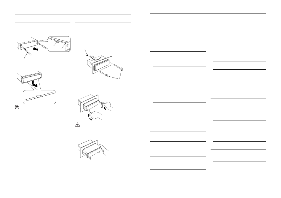
☞ Subscribe to SIRIUS. Refer to SIRIUS subscription> (page6). ? The power does not turn ON. ✔ The fuse has blown. ☞ After checking for short circuits in the wires, replace the fuse with one with the same ✔ The speaker wire has a short-circuit or touches the chassis of the vehicle, and then the protection and press the reset button. ? There’s a source you can’t switch. ✔ No subscription is established. ☞ Subscribe to SIRIUS. Refer to SIRIUS subscription> (page6). ✔ There’s no media inserted. ☞ Set the media you want to listen to. If there’s no media in this unit, you can’t switch to each ✔ The Disc changer isn’t connected. ☞ Connect the Disc changer. If the Disc changer isn’t connected to it’s input terminal, You can’t ? The memory is erased when the ignition is turned OFF. connected. section on ? There’s no loudness effect. ✔ You’re using Subwoofer preout. ☞ Loudness has no effect in Subwoofer preout. ? Even if Loudness is turned ON, high-pitched tone isn’t compensated for. ☞ High-pitched tone isn’t compensated for when in Tuner source. ? The TEL mute function does not work. ✔ The TEL mute wire is not connected properly. ☞ Connect the wire correctly, referring to the section on ? The TEL mute function turns ON even though the mute wire is not connected. car. part of the car. ? No sound can be heard, or the volume is low. ✔ The fader or balance settings are set all the way to one side. ✔ The input/output wires or wiring harness are connected incorrectly. wiring harness correctly. See the section on ✔ The values of Volume offset are low. ☞ Turn up the Volume offset, referring to the section on ✔ The ☞ Turn it OFF. ? The sound quality is poor or distorted. ✔ One of the speaker wires is being pinched by a screw in the car. ✔ The speakers are not wired correctly. ☞ Reconnect the speaker wires so that each output terminal is connected to a different ? The Touch Sensor Tone doesn’t sound. ✔ The preout jack is being used. ☞ The Touch Sensor Tone can’t be output from the preout jack. ? The Dimmer function doesn’t work. ✔ The Dimmer wire isn’t connected correctly. ☞ Check the Dimmer wire connection. ✔ The ☞ Turn it ON. Tuner source ? Radio reception is poor. ✔ The car antenna is not extended. ☞ Pull the antenna out all the way. ✔ The antenna control wire is not connected. ☞ Connect the wire correctly, referring to the section on ? The desired frequency can’t be entered with the Direct Access Tuning. ☞ Enter a station that can be received. ✔ You’re trying to enter a frequency with a 0.01 MHz unit. 0.1 MHz. Removing the Unit Removing the hard rubber frame 1 Engage the catch pins on the removal tool and remove the two locks on the upper level. 2 When the upper level is removed, remove the lower two locations. • The frame can be removed from the bottom side in the same manner. Removing the Unit 1 Refer to the section frame> (page 40) and then remove the hard 2 Remove the screw (M4 × 8) on the back panel. 3 Insert the two removal tools deeply into the slots on each side, as shown. 4 Lower the removal tool toward the bottom, and pull out the unit halfway while pressing towards • Be careful to avoid injury from the catch pins on the removal tool. 5 Pull the unit all the way out with your hands, being careful not to drop it. Catch Lock Accessory 2 Removal tool Accessory 2 Removal tool Screw (M4X8)
rating.
function is activated.
☞ Wire or insulate the speaker cable properly
source.
switch to an external disc source.
✔ The ignition and battery wire are incorrectly
☞ Connect the wire correctly, referring to the
✔ Tuner source is selected.
✔ The TEL mute wire is touching a metal part of the
☞ Pull the TEL mute wire away from the metal
☞ Center the fader and balance settings.
☞ Reconnect the input/output wires or the
☞ Check the speaker wiring.
speaker.
✔ A station that can’t be received is being entered.
☞ What can be designated in the FM band is to
Upper the frame and pull it forward as shown in
the figure.
rubber frame.
the inside.
(commercially available)