KVH Industries KVHTRACVISION G4 User Manual
Page 115
54-0147
108
TracVision G4 Technical Manual
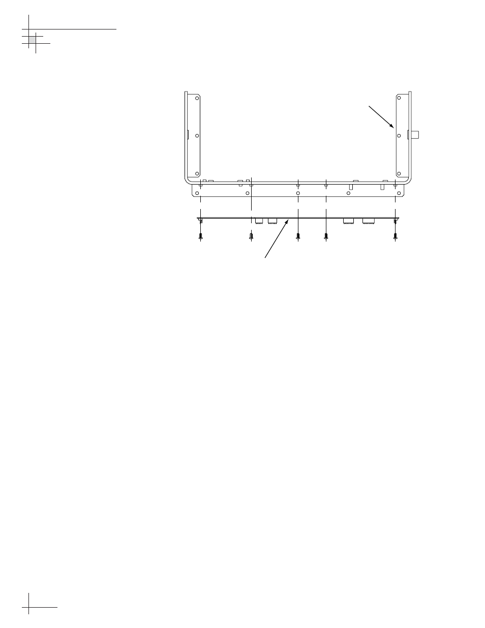
6. Remove the nine #6-32 screws that secure the PCB
to the antenna frame (see Figure 5-4).
7. Remove the PCB from the antenna frame.
8. Reverse this process to install the replacement
PCB. Reconnect all connectors removed in Step 5.
9. Reinstall the PCB cover.
10. Apply power to the antenna unit.
11. Type HALT
ENTER key).
12. Type DEBUGON
13. Type =TVG4HP
14. Type =SERNUM,
recorded in Step 2.
15. Type ZAP
16. Calibrate the antenna gyro as explained in
“Calibrating the Antenna Gyro” on page 112.
17. Reinstall your selected satellites as directed in
Section 2.9, “Installing Satellites Using the ADCU” on
page 44.
Figure 5-4
Main PCB Mounting (Top View)
Main PCB
Support Frame