Tk-8180, Terminal function – Kenwood TK-8180 User Manual
Page 48
TK-8180
48
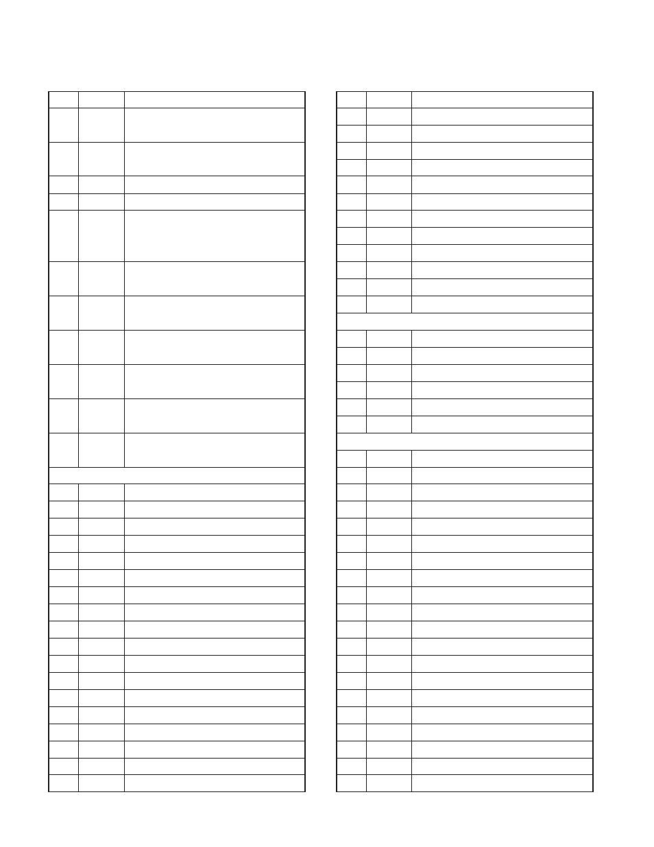
Pin No.
Name
Description
16
DTI
Data signal input.
Zin
≥22kΩ, 600±200mVp-p
17
TCTL
Speaker mute signal input.
Input : L
≤1.0V, H≥4.0V, Input voltage : 0V~5.0V
18
NC
Non-connection.
19
AUDIH
MIC mute signal input.
20
OPT2
Option boad I/F 2.
Output : L
≤0.45V, H≥4.7V/25kΩ load
Input : L
≤1.0V, H≥4.0V, Input voltage : 0V~5.0V
21
TXO
MIC signal output (AC coupled) before pre-
emphasis. Zo>2.2k
Ω, 130±50mVp-p typ.
22
RXEO
Audio signal output (DC coupled) after de-
emphasis. Zo>30k
Ω, 1±0.3Vp-p typ.
23
RXEI
Audio signal input (DC coupled) after de-
emphasis. Zin>15k
Ω, 1±0.3Vp-p typ.
24
TXI
MIC signal input (AC coupled) before pre-
emphasis. Zin>22k
Ω, 500±50mVp-p typ.
25
OPT6
Option boad I/F 6.
Output : L
≤0.45V, H≥4.7V/25kΩ load
26
8C
Power input after power switch.
8.0V typ, 100mA max
CN427 (to TX-RX unit A/3 CN701)
1
NC
Non-connenction.
2
SB
Power output after power switch.
3
SB
Power output after power switch.
4
SB
Power output after power switch.
5
SB
Power output after power switch.
6
SB
Power output after power switch.
7
SB
Power output after power switch.
8
AFO
RX filtered audio output.
9
DI
Data signal input.
10
5C
5V.
11
GND
Ground.
12
DEO
Detected signal output.
13
MI2
External MIC input.
14
ME
MIC ground.
15
GND
Ground.
16
RXD1
Serial data input 1.
17
AUXO2
AUX output 2.
18
TXD1
Serial data output 1.
Pin No.
Name
Description
19
AUXO1
AUX output 1.
20
AUXIO9
AUX input/output 9.
21
AUXIO5
AUX input/output 5.
22
AUXIO8
AUX input/output 8.
23
AUXIO4
AUX input/output 4.
24
TXD2
Serial data output 2.
25
AUXIO3
AUX input/output 3.
26
RXD2
Serial data input 2.
27
AUXIO2
AUX input/output 2.
28
AUXIO1
AUX input/output 1.
29
AUXIO7
AUX input/output 7.
30
AUXIO6
AUX input/output 6.
CN428
1
SB
Power output of switched power supply.
2
SPI
Speaker output.
3
SPO
Speaker input.
4
PA
Control signal output of PA function.
5
HOR
Control signal output of Horn alert function.
6
GND
Ground.
CN429 (to Display unit CN902)
1
(DM)
Reserve.
2
GND
Ground.
3
RXD
Serial data signal input.
4
TXD
Serial data signal output.
5
NC
Non-connenction.
6
5C
5V output.
7
SHIFT/MODEL
Control signal output of beat-shift function.
8
(CLK)
Reserve.
9
(LCDDO)
Reserve.
10
(LCDDI)
Reserve.
11
(LCDRST)
Reserve.
12
RST2
Reset signal output.
13
PSENS
Detection signal input of display unit.
14
GND
Ground.
15
ME
MIC ground.
16
MIC
MIC signal input.
17
GND
Ground.
18
GND
Ground.
19
PSW
Detection signal input of power switch.
20
NC
Non-connenction.
TERMINAL FUNCTION