Function for compatibility mode, 135 appendix – Star Micronics SP298 Series User Manual
Page 138
135
APPENDIX
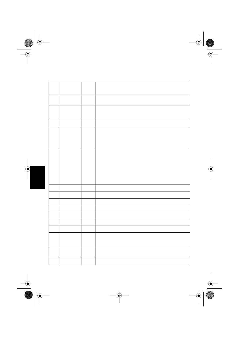
Function for compatibility mode
Pin
No.
Signal Name
IN/OUT
Function
1
nStorobe
IN
Signals when data is ready to be read. Signal goes from HIGH to LOW
(for at least 0.5 microsec.) when the data is available.
2-9
Data0-7
IN
These signals provide the information of the first to eighth bits of
parallel data. Each signal is at HIGH level for a logical 1 and at a LOW
level for a logical 0.
10
nAck
OUT
A 9 microsecond LOW pulse acknowledges receipt of the data.
11
Busy
OUT
When this signal goes to LOW, the printer is ready to accept data. When
the printer is in one of the conditions below, “HIGH” is set.
1. Data is being entered
2. Off line
3. Error condition
12
PError
OUT
This signal indicates the status of the paper sensor.
[In Star mode]
This signal goes to HIGH when either the TOF or the BOF sensor
detects that there is no paper. The signal will go to LOW when both the
TOF and BOF sensor detect that there is paper installed.
[In the ESC/POS mode]
This signal outputs the status of the sensor selected using the
“c3” command.
13
Select
OUT
This signal is HIGH when the printer is online.
14
nAutoFd
IN
Unused
15
N/C
Unused
16
GND
Signal ground
17
Flame GND
Chassis ground, isolated from logic ground
18
Logic High
3.9 k
Ω
pull-up
19-30
GND
Twisted pair return the signal to ground level.
31
nInit
IN
This becomes a reset signal when DIP switch 1 is set to ON. (See page 128
for details.) When this signal goes to LOW (for at least 0.5 microsec.), the
printer is reset to its power-on condition.
32
nFault
OUT
This signal is normally HIGH. This signal goes to LOW to signal that
the printer cannot print due to an error condition.
33
EXT GND
External ground