4x registers – Schneider Electric 170AMM11030 User Manual
Page 15
31005009 01 November 2003
15
Words 4 ... 5
Analog Fail State Value Register
The module always expects two words of user defined data, even if the data is not
used. The first word of the user shutdown field is used for channel 1, the second for
channel 2.
Word 6
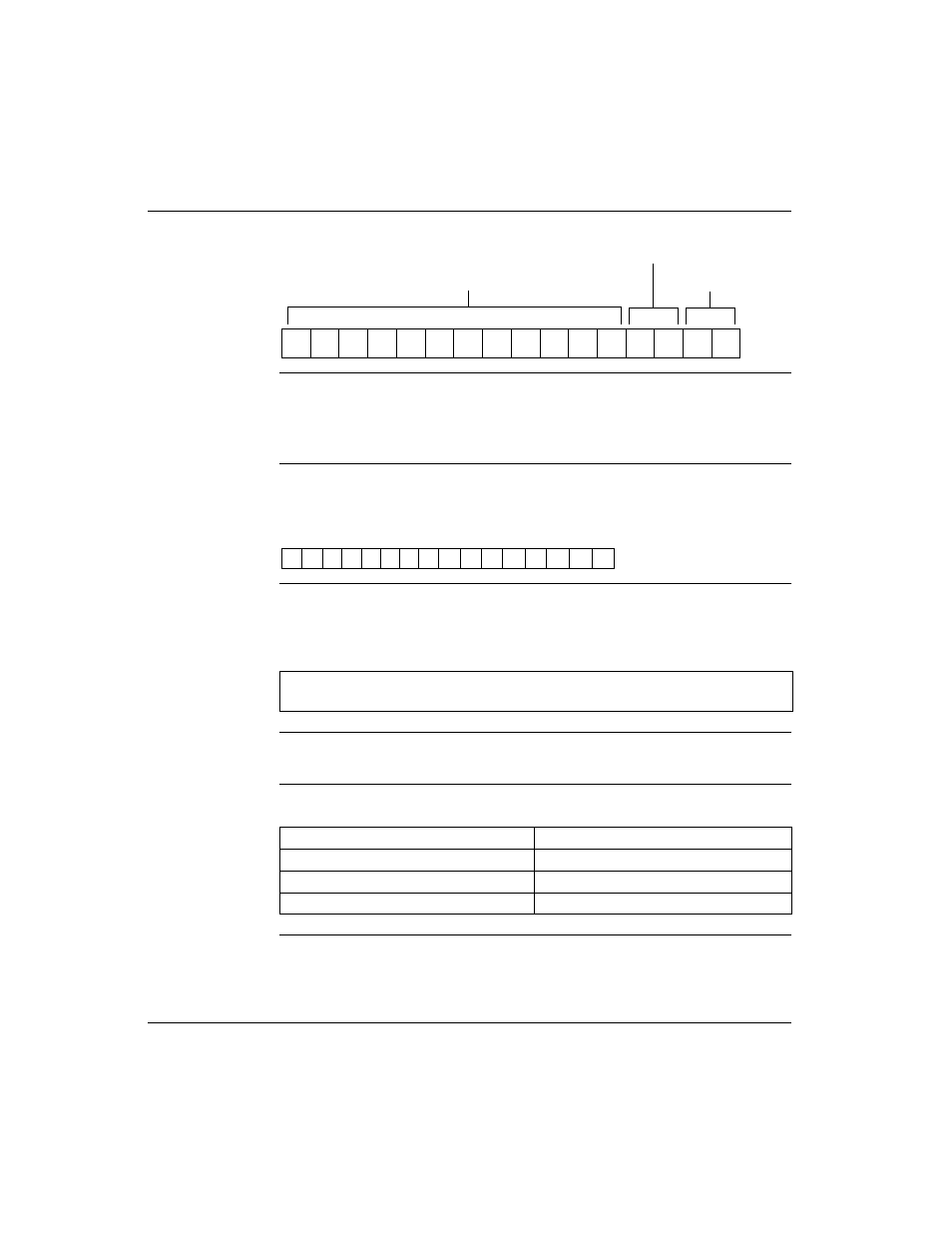
Discrete Output Register
This word contains a right justified binary eight bit data field.
Words 7 ... 8
Map to Analog Output Register
Each word in this range contains a left justified binary 15 bit data field. The range is
0 ... 7FFE hex (0 ... 32766 decimal), but the resolution is only 14 bit.
4x Registers
Overview
The 4x registers traffic copped to this module are used for output data as follows.
15
14
13
12
11
10
9
8
7
6
5
4
3
2
1
0
Not Used
Channel 1
Channel 2
8 7 6 5 4 3 2 1
15 14 13 12 11 10 9 8 7 6 5 4 3 2 1 0
Note: If a user shutdown value is greater than the count range for the channel, then
the count range maximum value will be used as the shutdown value.
I/O Map Register
Data Type
4x + 5
Data for discrete output
4x + 6
Data for analog output channel 1
4x + 7
Data for analog output channel 2