I/o map – Schneider Electric 170AMM11030 User Manual
Page 12
12
31005009 01 November 2003
Analog I/O
Devices
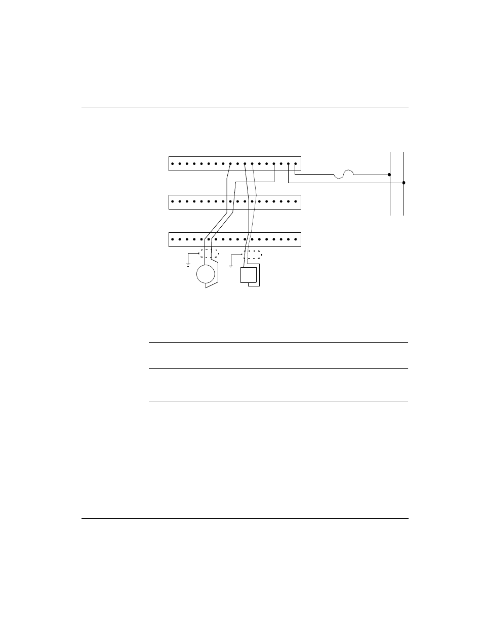
The diagram below shows field wiring for analog input and analog output devices.
Recommended fuses:
l
F3: Use a 1A fuse, Wickman 19181-1A or equivalent.
I/O Map
I/O Map Module
Configuration
The module must be I/O mapped as 8 contiguous input words and 8 contiguous
output words.
Row 2
Row 3
Row 4
Analog Actuator
(Output Devices)
Analog Sensor
(Input Devices)
16
-4
2 V
D
C
16-
42 V
D
C
R
e
tu
rn
AI1
AI2
AO1+
AO1-
AO2+-AGND
L+
AO2-
M-
+
−
F3