Belt replacement – Snapper 1300 Series User Manual
Page 35
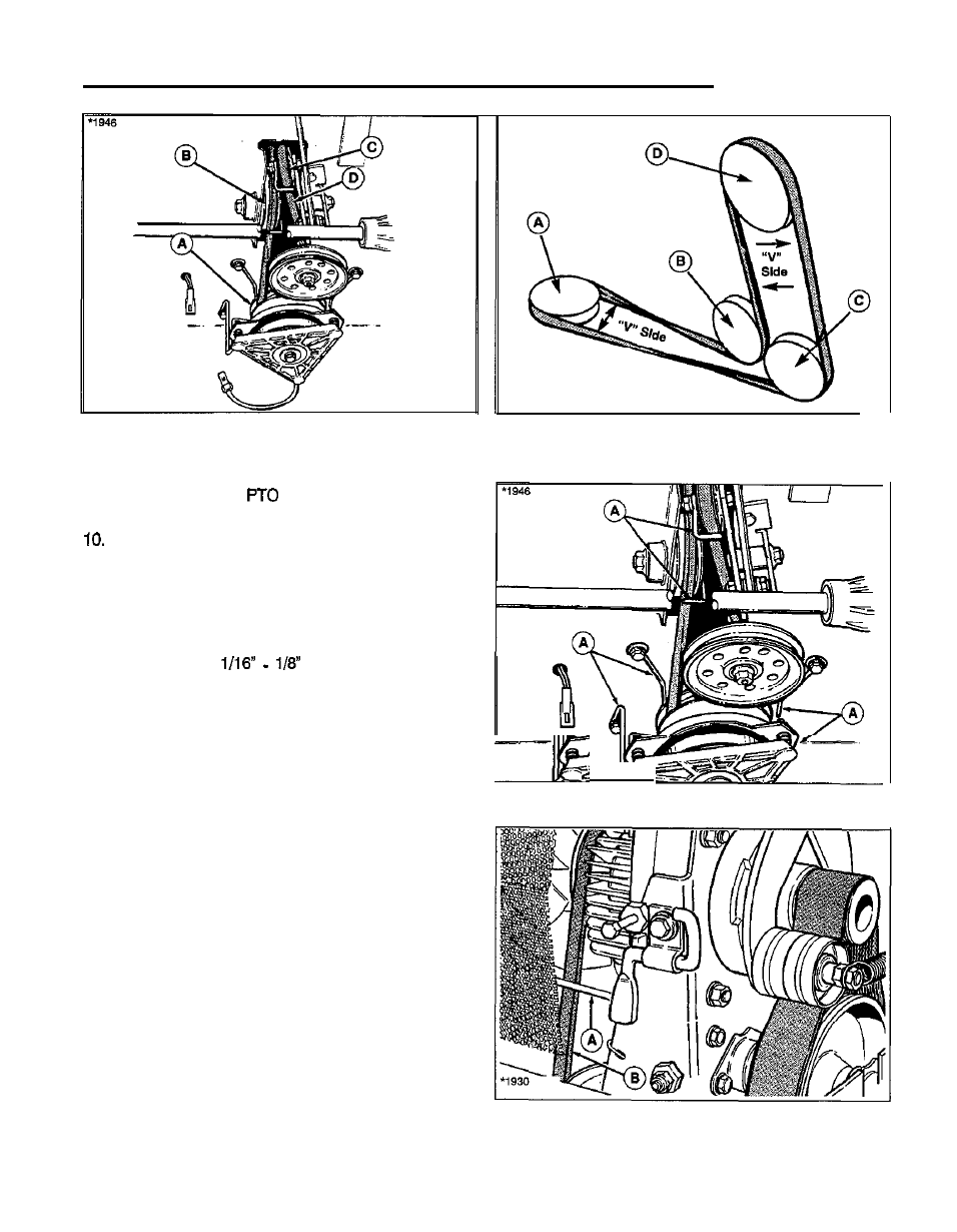
Belt Replacement
Figure 48. V Belt (Shown from Underside of Rider)
A. Engine Pulley
C. Idler Pulley
B. Fixed Pulley
D. Belt
9. Install mower belt to
pulley. Follow the proce-
dures under
Mower Belt.
Install fan with original hardware. Note that a
tab on
the inner side of the fan fits into a hole when the fan is
properly installed.
11. Install the screen (A, figure 44) with two capscrews at
top and two capscrews at bottom.
12. Release parking brake to check belt stop adjustment.
There should be
clearance between belt
and belt stops. Five belt stops are shown in figure 47.
13. See figure 48. Check belt stop at transmission pulley.
To adjust, loosen mounting hardware, position belt
stop, then tighten hardware.
14. Perform Clutch/Brake Adjustment as described in the
Adjustments section.
Figure 48. Belt Pattern (Seen from R.H. Side)
A. Engine Pulley
C. Idler Pulley
B. Fixed Pulley
D. Transmission Pulley
Figure 47. Belt Stop Locations
A. Belt Stops
Figure 48. Transmission Pulley Belt Stop Location
A. Belt Stop
B. V Belt
31