Belt replacement, Rider drive belt – Snapper 1300 Series User Manual
Page 34
Belt Replacement
5. Remove anti-spin rod from frame and PTO. See figure
41.
6. Remove belt from PTO pulley. See figure 42.
Hardware securing belt stops may have to be loos-
ened in order to remove belt.
7. Remove belt from mower deck and replace with a new
belt. Check belt pattern as shown in figure 43.
6. See figure 42. Make sure mower belt goes underneath
rider, and over
the drive
axle. Install belt around bot-
tom pulley of PTO.
A
CAUTION
FRONT
Anti-spin rod must be reinstalled for operation.
PTO will be Immediately damaged if operated
without anti-spin rod.
I
9. See figure 42. Install anti-spin rod to PTO. Insert other
end through frame and secure with spring clip.
10. Connect wiring harness to PTO and secure it to the
belt stop with ties.
Pull spring-loaded idler pulley back to gain slack, and
install belt on idler pulley. See figure 39.
A
WARNING
To avoid personal injury, use caution when mov-
ing spring-loaded pulley (A, figure 40). Spring
tension is strong. Do not remove belt
from
spring-loaded idler pulley (A). Remove belt from
left and right idler pulleys (C
D).
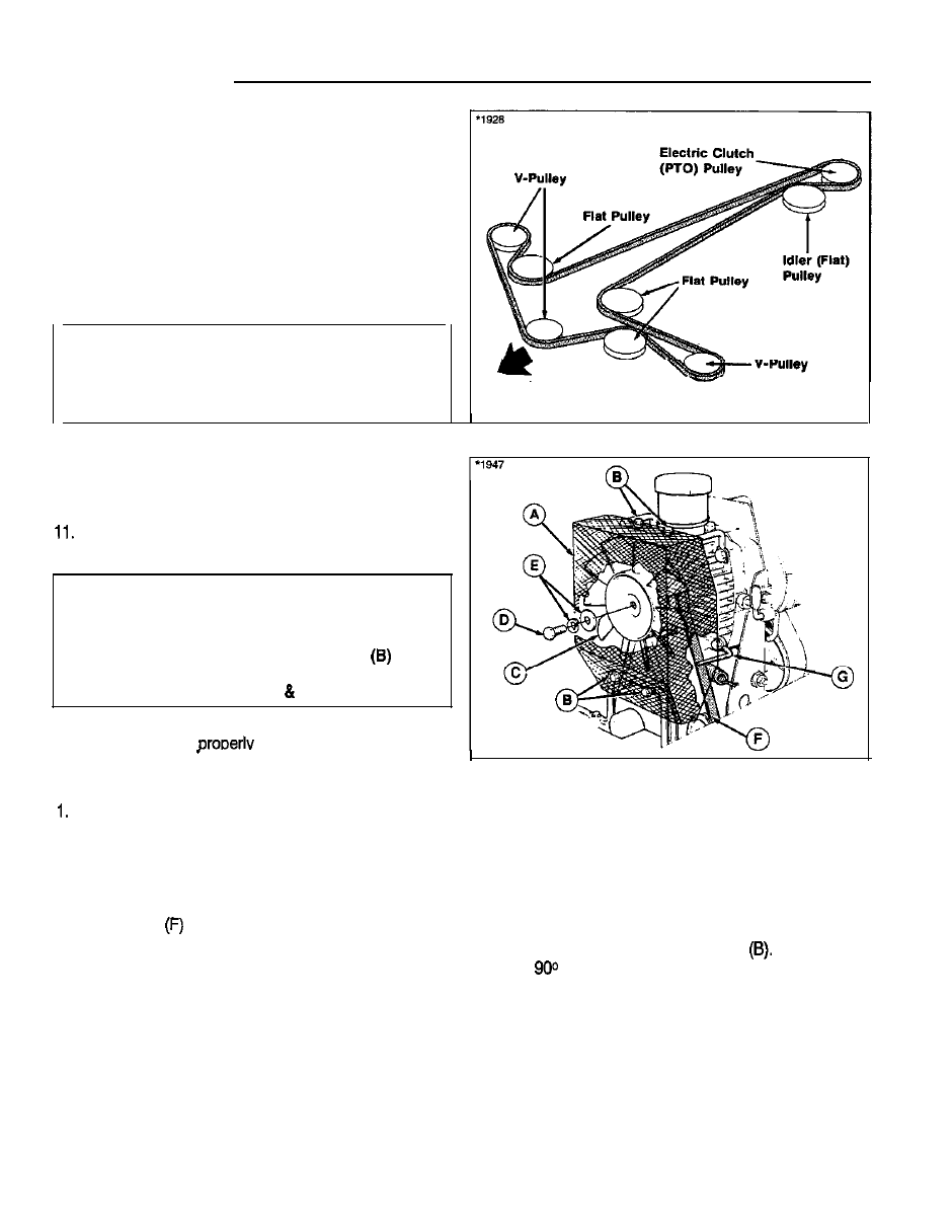
Figure 43. Mower Belt Routing
12. Install belt covers. See figure 37. Make sure covers
and deflector are
installed before ooeration.
RIDER DRIVE BELT
Set the parking brake to provide slack in the belt.
2. See figure 44. Remove the screen (A) by removing
four capscrews (B); two at top and two at bottom.
3. Remove the fan (C) by removing one screw (D) in cen-
ter. Keep washers (E) in proper order for reassembly.
4. Slip the belt
from the transmission pulley.
5. See figure 45. Remove belt (D) from idler pulley (C),
fixed pulley (B) and engine pulley (A). Loosen belt
stops as necessary.
6. Remove mower belt from PTO pulley by following the
procedure under Mower Belt.
Figure 44 Hydro Pump
A. Screen
E. Washers
B. Capscrews
C. Fan
D. Capscrews
F. Belt
G. Belt Stop
7. See figure 46. Place the new belt onto the engine pul-
ley (A), fixed pulley (B) and idler pulley (C). Note that
the V side of belt rides in the pulley grooves and the
flat side rides against the fixed pulley
The belt
turns
between engine pulley and the fixed pulley
(B), and between engine pulley and idler pulley (C).
8. Pull belt up from top and place onto the transmission
pulley (D, figure 46)
3 0