Mower removal – Snapper 1300 Series User Manual
Page 14
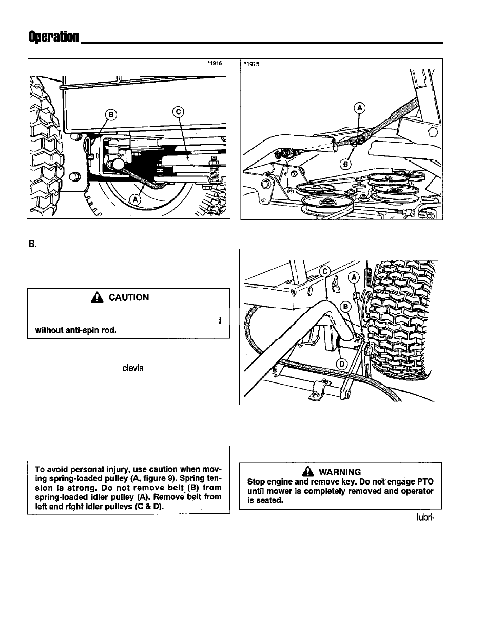
Figure 6. Anti-Spin Rod
A. Anti-Spin Rod
c. PTO
Spring Clip
5. Connect top and bottom halves of mower lift arms.
See figure 7.
Anti-spin rod must be installed for operation
PTO will be immediately damaged if operated
6. Install mower hitch arms to rider hitch arms. See fig-
ure 8. Make sure large washer (D) is placed on rider
hitch arms. Secure with
pins and spring clips.
7. See figure 9. Connect top link of chains (E) to weld
studs and secure with washers and cotter pins.
6. Install belt on right-hand and left-hand idler pulley by
pulling on spring-loaded idler pulley (A, figure 9).
9. Check mower belt routing carefully. Belt should be
positioned as shown in figure 10.
1
A
WARNING
Figure 7. Lift Arm Halves
A. Weld Stud
B. Spring Clip
1914
I
Figure 8. Hitch Arms
A. Spring Clip
C. Mower Hitch Arm
B. Clevis Pin
D. Washer
MOWER REMOVAL
10. Make sure deflector is properly installed.
1. Mower can be easily removed and installed for
cation, service and year-end storage.
2. Remove hardware securing belt covers to mower
deck. Refer to figure 12. Remove belt covers.
Diagram is located on underside of belt cover.
10