3 tem pe ra ture moni to ring 65, 4 error sta tus regis ter 65, Er ror sta tus re gis ter 65 – Samson 5476 User Manual
Page 65: Ex cess tem pe ra tu re alarm 65, Tem pe ra tu re mo ni to ring 65, Temperature monitoring, Error status register, 3 temperature monitoring, 4 error status register
8.3
Temperature monitoring
Should a deviation arise in a control circuit that is greater than 10 °C for longer than 30 min-
utes, the bit D12 is automatically set in the error status register.
If this function is not required, configure FB36 = ON, select “steig“ and leave the input BE8
unswitched.
8.4
Error status register
The error status register is used to indicate controller or system errors. In modem operation with
Dial-up also upon corrected fault function, any change in state of the error status register causes
the building control station to be dialed.
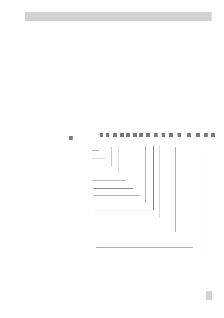
BITMAP error status register (FSr)
Number = Bit no. in HR
0 1 2 3 4 5 6 7 8 9 10 11 12 13 14 15
A set bit is indicated by
on the
right of number
2
0
2
1
2
2
2
3
2
4
2
5
2
6
2
7
2
8
2
9
2
10
2
11
2
12
2
13
2
14
2
15
Sensor breakage
D_0
Default values read
D_1
DHW set point not reached
D_2
Mode switch HK faulty
D_3
Mode switch DHW faulty
D_4
1)
BE1 = active + (FB43 = ON)
D_5
1)
BE2 = active + (FB42 = ON)
D_6
1)
BE3 = active + (FB41 = ON)
D_7
1)
BE4 = active + (FB40 = ON)
D_8
1)
BE5 = active + (FB39 = ON)
D_9
1)
BE6 = active + (FB38 = ON)
D_10
1)
BE7 = active + (FB37 = ON)
D_11
1)
BE8 = active + (FB36 = ON)
D_12
Data error alarm from WMZ
D_13
Meter bus communication error D_14
Unauthorized access
D_15
1)
The binary inputs BE1 to BE8 appear in the error status register whenever the associated function
block FB_ = ON
EB 5476 EN
65
Operational faults