Control block utilization, Cte display implementation – Schneider Optics Web Embedded Server User Manual
Page 48
The MSTR Instruction
38
840 USE 115 00 Version 1.0
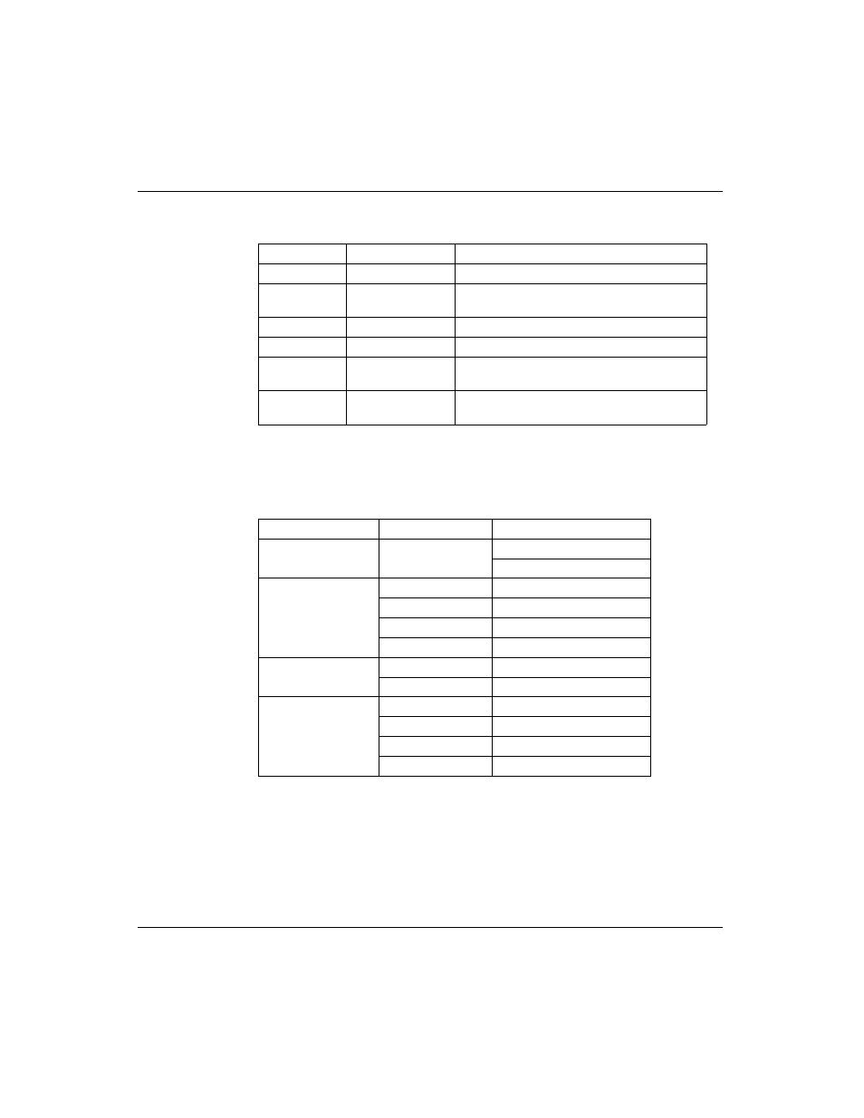
Control Block
Utilization
The registers in the MSTR control block (the top node) contain the Read CTE
information as described in the following table:
CTE Display
Implementation
The values in the Ethernet configuration extension table (CTE) are displayed in a
series of registers in the middle node of the MSTR instruction when a Read CTE
operation is implemented. The middle node contains the first of 11 contiguous 4x
registers. The registers display the following CTE data:
Register
Function
Content
Displayed
Operation Type
11
First implied
Error status
Displays a hex value indicating an MSTR error,
when relevant.
Second implied Not applicable
Third implied
Not applicable
Fourth implied
Low byte
Quantum backplane slot address of the web
embedded server module.
Fifth ... Eight
implied
Not applicable
Parameter
Register
Content
Frame type
Displayed
1 = 802.3
2 = Ethernet
IP Address
First implied
First byte of the IP address
Second implied
Second byte of the IP address
Third implied
Third byte of the IP address
Fourth implied
Fourth byte of the IP address
Subnetwork mask
Fifth implied
Hi word
Sixth implied
Low word
Gateway
Seventh implied
First byte of the gateway
Eighth implied
Second byte of the gateway
Ninth implied
Third byte of the gateway
Tenth implied
Fourth byte of the gateway