Middle node content, Bottom node content, 3 mstr function error codes – Schneider Optics Web Embedded Server User Manual
Page 38: Tcp/ip ethernet error codes, Mstr function error codes
The MSTR Instruction
28
840 USE 115 00 Version 1.0
Middle Node
Content
The 4x register entered in the middle node is the first in a group of contiguous
holding registers that comprise the data area. For operations that provide the
communication processor with data such as a Write operation, the data area is the
source of the data. For operations that acquire data from the communication
processor, such as a Read operation, the data area is the destination for the data.
In the case of the Ethernet Read and Write CTE operations (see sections 3.2.11
and 3.2.12), the middle node stores the contents of the Ethernet configuration
extension table in a series of registers.
Bottom Node
Content
The integer value entered in the bottom node specifies the length - the maximum
number of registers in the data area. The length must be in the range 1 ... 100.
3.2.3
MSTR Function Error Codes
If an error occurs during an MSTR operation, a hexadecimal error code will be
displayed in the first implied register in the control block (the top node). Function
error codes are network-specific.
TCP/IP Ethernet
Error Codes
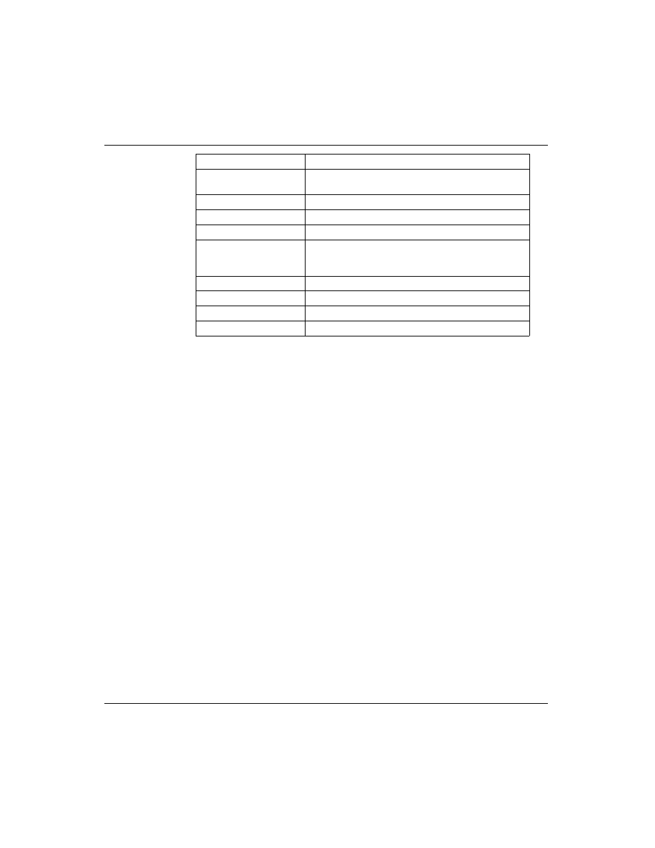
An error in an MSTR routine over TCP/IP Ethernet may produce one of the
following errors in the MSTR control block:
Register
Content
Displayed
Identifies one of ten MSTR operations legal for TCP/IP
(1 ... 4 and 7 ... 12).
First implied
Displays error status.
Second implied
Displays length (number of registers transferred).
Third implied
Displays MSTR operation-dependent information.
Fourth implied
High byte: Destination index.
Low byte: Quantum backplane slot address of the web
embedded server module.
Fifth implied
Byte 4 of the 32-bit destination IP Address.
Sixth implied
Byte 3 of the 32-bit destination IP Address.
Seventh implied
Byte 2 of the 32-bit destination IP Address.
Eight implied
Byte 1 of the 32-bit destination IP Address.