Location and function of parts and controls, Front panel, Location and function of – Sony DMX-P01 User Manual
Page 8: Parts and controls
8
Location and Function of Parts and
Controls
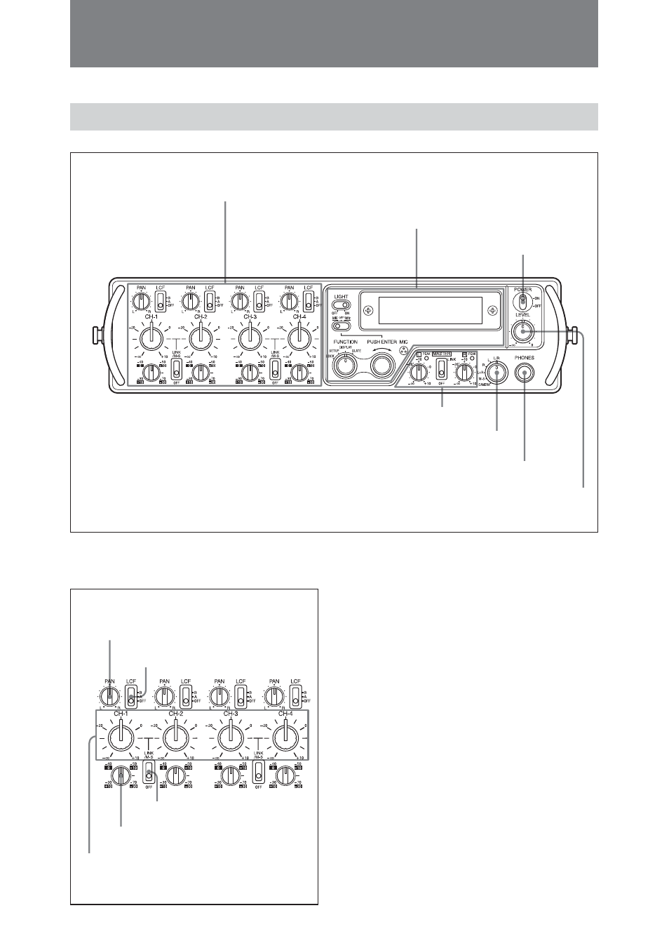
Front Panel
1
Input section
2
Digital function section
3
Power switch
4
LEVEL control
5
PHONES connector
6
Headphones monitor mode switch
7
Output section
1
Input section
1
PAN control
Adjusts the mix level of the input
signal sent to the Left and Right buses.
The adjustable range is 0 dB to –3 dB
(at the center position) to -
∞
.
When the control is turned fully to
the L side: The signal is sent to the
Left bus at a 0 dB gain. The signal
to the Right bus is completely
attenuated
When the control is turned fully to
the R side: The signal is sent to the
Right bus at a 0 dB gain. The
signal to the Left bus is completely
attenuated.
When the control is placed at the
center position: A signal of –3 dB
is sent to both the Left and Right
buses.
1
PAN control
2
LCF switch
3
Input level control
4
Input gain control
5
LINK/M-S switch