Circuit adjustments, Electrical adjustments – Sony KP-41S5U User Manual
Page 22
– 22 –
KP-41S5/41S5B/41S5G/
41S5K/41S5R/41S5U
RM-862
5-1. ELECTRICAL ADJUSTMENTS
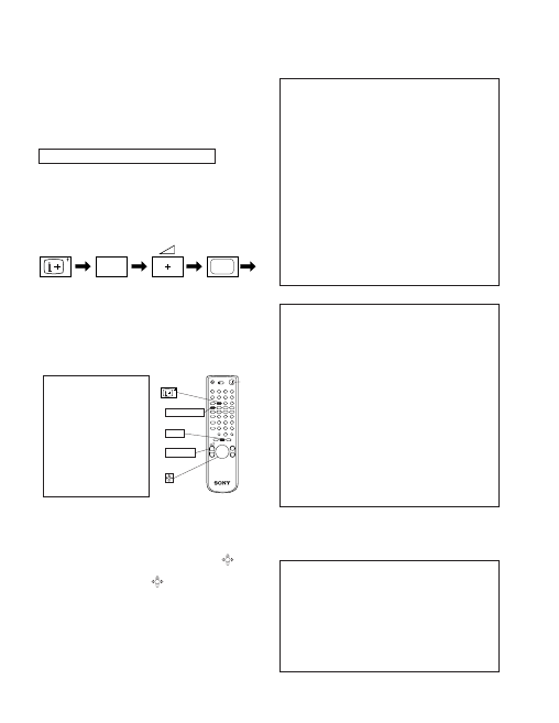
HOW TO ENTER INTO SERVICE MODE
1. Turn on the main power switch of the set and enter into
standby mode.
2. Press the following sequcnce of buttons on the Remote
Commander.
Service adjustment to this model can performed with the sup-
plied remote commander RM-862.
“TT—” will appear in the top right comer of the screen.
Other status information wull also be displayed.
3. Press MENU on the commander to obtain the following
menu on the screen.
5
(ON SCREEN
DISPLAY)
(DIGIT 5)
(VOLUME +)
(TV)
PICTURE ADJUSTMENT
AFC mode
2
REF position
2
SCP BGR
1
SCP BGF
1
Trap Fo
0
Sub contrast
Adj
Sub colour
Adj
Sub brightness
Adj
Green drive
Adj
Blue drive
Adj
Green cutoff
Adj
Blue cutoff
Adj
Gamma
0
Pre / overshoot
0
Y delay
3
GEOMETRY ADJUSTMENT in 4 : 3 mode
UP Corn Pin
Adj
V Size
Adj
V Position
Adj
S Correction
Adj
V Linearity
Adj
H Size
Adj
H Position
Adj
Pin Amp
Adj
Pin Phase
Adj
AFC Bow
Adj
AFC Angle
Adj
EHT V
Adj
EHT H
Adj
Corner Pin
Adj
LO Corn Pin
Adj
WIDE
V Aspect
47
V Scroll
31
Upper V Lin
0
Lower V Lin
0
Left Blanking
1
Right Blanking
11
TEST MENU
> picture adjustment
Geometry
Wide
MSP
IC status
Current TV status
Convergence
™
1
2
3
4
5
8
6
7
10
9
Standby
TV POWER ON
VOLUME
+
MENU
RM-862
+
–
4. Move to the correspondind adjustment using the
button
on the commander.
5. Move the button to the right
to enter the selected
adjustment.
6. Before TURN OFF is neccessary:
[DATA WRITE], [DATA COPY] in 4 : 3 and 16 : 9 mode.
7. Turn off the power to quit the service mode when adjust-
ments are completed.
SECTION 5
CIRCUIT ADJUSTMENTS
*
*
: Adjust only if AE board change.
For change CRT R-G-B is better CONVERGENCE
don't change in 16 : 9 mode.