Exploded views, Chassis section – Sony Ericsson CDX-M620 User Manual
Page 56
56
CDX-M620/M670
3
4
1
2
9
6
7
5
8
8
A
A
#2
#2
CN901
#2
#2
#2
MG-383Z-121//K
#1
#1
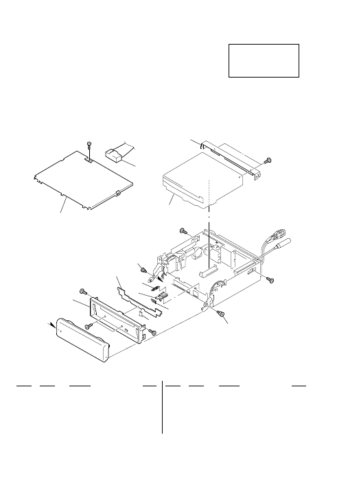
SECTION 5
EXPLODED VIEWS
Ref. No.
Part No.
Description
Remark
5-1. CHASSIS SECTION
Ref. No.
Part No.
Description
Remark
The components identified by
mark 0 or dotted line with mark
0 are critical for safety.
Replace only with part number
specified.
NOTE:
• The mechanical parts with no reference
number in the exploded views are not supplied.
• Items marked “*” are not stocked since
they are seldom required for routine service.
Some delay should be anticipated
when ordering these items.
• -XX and -X mean standardized parts, so
they may have some difference from the
original one.
• Color Indication of Appearance Parts
Example :
KNOB, BALANCE (WHITE) ... (RED)
Parts Color Cabinet’s Color
• Accessories and packing materials and
hardware (# mark) list are given in
the last of this parts list.
R
R
* 1
3-230-511-01 COVER
2
1-776-207-72 CORD (WITH CONNECTOR) (POWER) (US)
2
1-776-527-71 CORD (WITH CONNECTOR) (ISO) (POWER)
(AEP,UK,E)
3
X-3380-551-1 PANEL (CD) SUB ASSY, SUB (M670:US)
3
X-3380-552-1 PANEL (CD) SUB ASSY, SUB (M620)
3
X-3380-554-1 PANEL (CD) SUB ASSY, SUB (AEP,UK,E)
* 4
1-681-373-11 SUB (CD) BOARD
5
3-230-515-01 SLIDER (FLEXIBLE)
6
3-230-514-01 COVER (FLEXIBLE)
7
3-230-516-01 SPRING (FLEXIBLE), TENSION
8
3-045-756-01 SCREW (PANEL)
* 9
3-045-743-01 BRACKET (CD)
CN901
1-783-268-11 CABLE, FLAT 11P