Disassembly, Front panel assy (normal), Front panel assy (inoperative) – Sony Ericsson CDX-M620 User Manual
Page 16: Cd mechanism block, front panel (key) assy
16
16
CDX-M620/M670
3
screw (panel)
flexible board
5
1
6
front panel (key) assy
(Take care not to pull the
flexible board excessively)
4
screw (panel)
2
front panel (DSPL) assy
4
screw (panel)
3
front panel (DSPL) assy
2
1
Turn on the power and open the front panel.
stand
5
screw (panel)
6
front panel (key) assy
(Take care not to
pull the flexible
board excessively)
flexible board
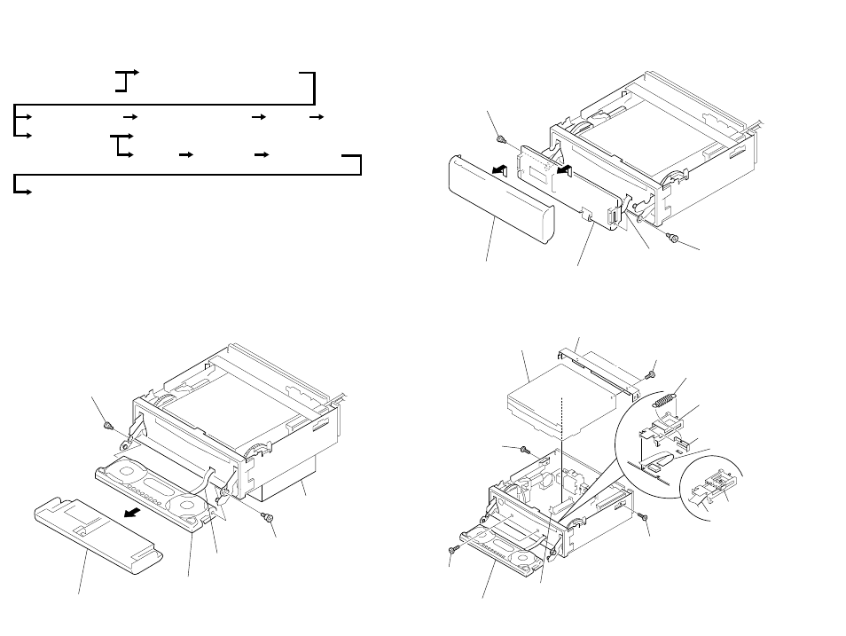
SECTION 2
DISASSEMBLY
Note : This set can be disassemble according to the following sequence.
Note : Follow the disassembly procedure in the numerical order given.
2-1. FRONT PANEL ASSY (NORMAL)
2-2. FRONT PANEL ASSY (INOPERATIVE)
2-3. CD MECHANISM BLOCK, FRONT PANEL (KEY) ASSY
Front Panel Assy (Normal)
Front Panel Assy (Inoperative)
CD Mechanism Block, Front Panel (KEY) Assy
Sub Panel (CD) Sub Assy
Motor Block Assy, Cam (R) Assy
Shaft Roller Assy
Floating Block Assy
Optical Pick-up Block
Main Board
Heat Sink
Chassis (T) Sub Assy
Lever Section
Servo Board
2
PTT 2.6x4
4
CN401
qa
front panel (key) assy
1
PTT 2.6x6
3
PTT 2.6x4
5
CD mechanism block
7
bracket (CD)
6
PTT 2.6x6
8
tension spring (flexible)
flexible board
9
slider (flexible)
slider (flexible)
0
cover (flexible)
qa
CN604
Note: When installing
the flexible board,
make the board slack
as illustrated.