Installing the new water heater (cont’d), Warning – State SDV 75 70 NE/PE User Manual
Page 19
19
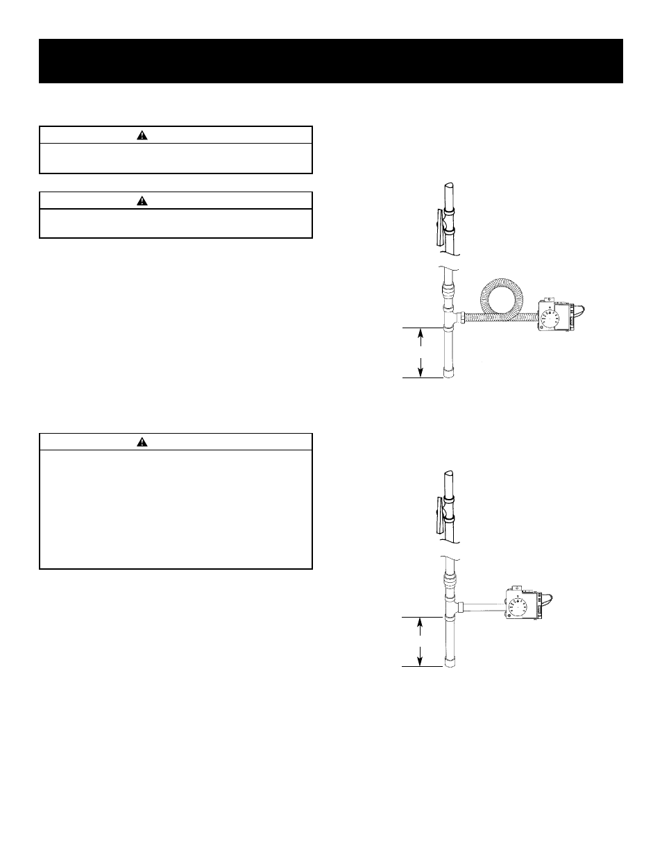
Connecting the gas piping to the gas control valve of the
water heater can be accomplished by either of the two
methods shown.
SEDIMENT TRAP
A sediment trap shall be installed as close to the inlet of the
water heater as practical at the time or water heater instal-
lation. The sediment trap shall be either a tee fitting with a
capped nipple in the bottom outlet or other device recog-
nized as an effective sediment trap. If a tee fitting is used, it
shall be installed in conformance with one of the methods
of installation shown.
Installing the New Water Heater (cont’d)
GAS PIPING WITH
FLEXIBLE CONNECTOR
GAS PIPING WITH ALL BLACK IRON PIPE TO
GAS CONTROL
GROUND JOINT
UNION (OPTIONAL)
MANUAL
SHUTOFF
VALVE
GAS
CONTROL
VALVE
GAS SUPPLY PIPING
FLEXIBLE GAS CONNECTOR
LABELED AS COMPLYING
WITH ANSI STANDARDS
LOOP
DRIP LEG
(SEDIMENT TRAP)
CAP
GAS SUPPLY PIPING
MANUAL
SHUTOFF
VALVE
GAS
CONTROL
VALVE
BLACK PIPE
DRIP LEG
(SEDIMENT
TRAP)
CAP
3
″ MIN.
3
″ MIN.
GROUND JOINT
UNION (OPTIONAL)
WARNING
Contaminants in the gas lines may cause improper oper-
ation of the gas control valve that may result in fire or
explosion. Before attaching the gas line be sure that all
gas pipe is clean on the inside. To trap any dirt or foreign
material in the gas supply line, a drip leg (sometimes
called a sediment trap) must be incorporated in the pip-
ing. The drip leg must be readily accessible. Install in
accordance with the “Gas Piping” section. Refer to the
latest edition of the National Fuel Gas Code, ANSI
Z223.1, also referred to as NFPA 54.
WARNING
Use pipe joint compound or teflon tape marked as being resis-
tant to the action of petroleum [Propane (L.P.)] gases.
WARNING
The appliance and its gas connection must be leak tested
before placing the appliance in operation.