Installing the new water heater (cont'd), Venting (cont'd) – State SDV 75 70 NE/PE User Manual
Page 17
17
Installing the New Water Heater (cont'd)
Venting (cont'd)
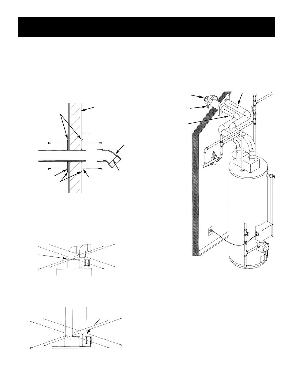
INSTALLATION SHOWING USE OF PVC, ABS OR
CPVC PIPE FOR INLET AND OUTLET VENT PIPING:
Inlet piping through any type wall.
EXTERIOR WALL
SILICONE
SEALER
SILICONE SEALER
SCREW
SCREW
SCREW
SCREW
SCREEN AT
OUTLET
FLUE MOUNTING
ADAPTOR
VENT CAP MUST
BE POSITIONED
DOWNWARD
1
1
⁄
2
" MIN. EXTENSION
THROUGH
EXTERIOR WALL
FLUE MOUNTING ADAPTOR
CONNECTING VENT TO BLOWER
1. If making an immediate horizontal run of vent off the
blower, one 3
″ PVC inlet and one 3″ ABS outlet
Schedule 40 street elbows are required. Place the elbow
in the required direction on the blower and using 3 sheet
metal screws, attach the elbow.
2. If there is to be a vertical run of vent from the blower, the
3
″ PVC inlet and the 3″ ABS outlet pipes must be
attached to the blower and venting hood, using 6 sheet
metal screws.
CAULK
JOINTS
CAULK
JOINTS
VENT TO
OUTDOORS
INTAKE FOR
COMBUSTION AIR
FLUE PRODUCTS
DISCHARGE PIPE
AIR INTAKE
PIPE
INSTALLATION SHOWING USE OF (OPTIONAL)
DELUXE HORIZONTAL VENT KIT:
Typical installation.
If this concentric flue, through the wall type of venting
system is preferred, the vent kit can be ordered from the
Service Parts Dept. under kit #9002749. See also pages 36
and 37. Installation instructions are provided with the kit.
VENTING THROUGH A ROOF
Two 3
″ inlet and outlet PVC Schedule 40 45° vent caps are
supplied.
A 5’ section of 3
″ ABS Schedule 40 outlet vent pipe is sup-
plied. More may be required and must be supplied locally.
1. The water heater requires its own (separate) venting
system.