Cable assembl y – Sears 831.159460 User Manual
Page 12
25
22
23
24
22.
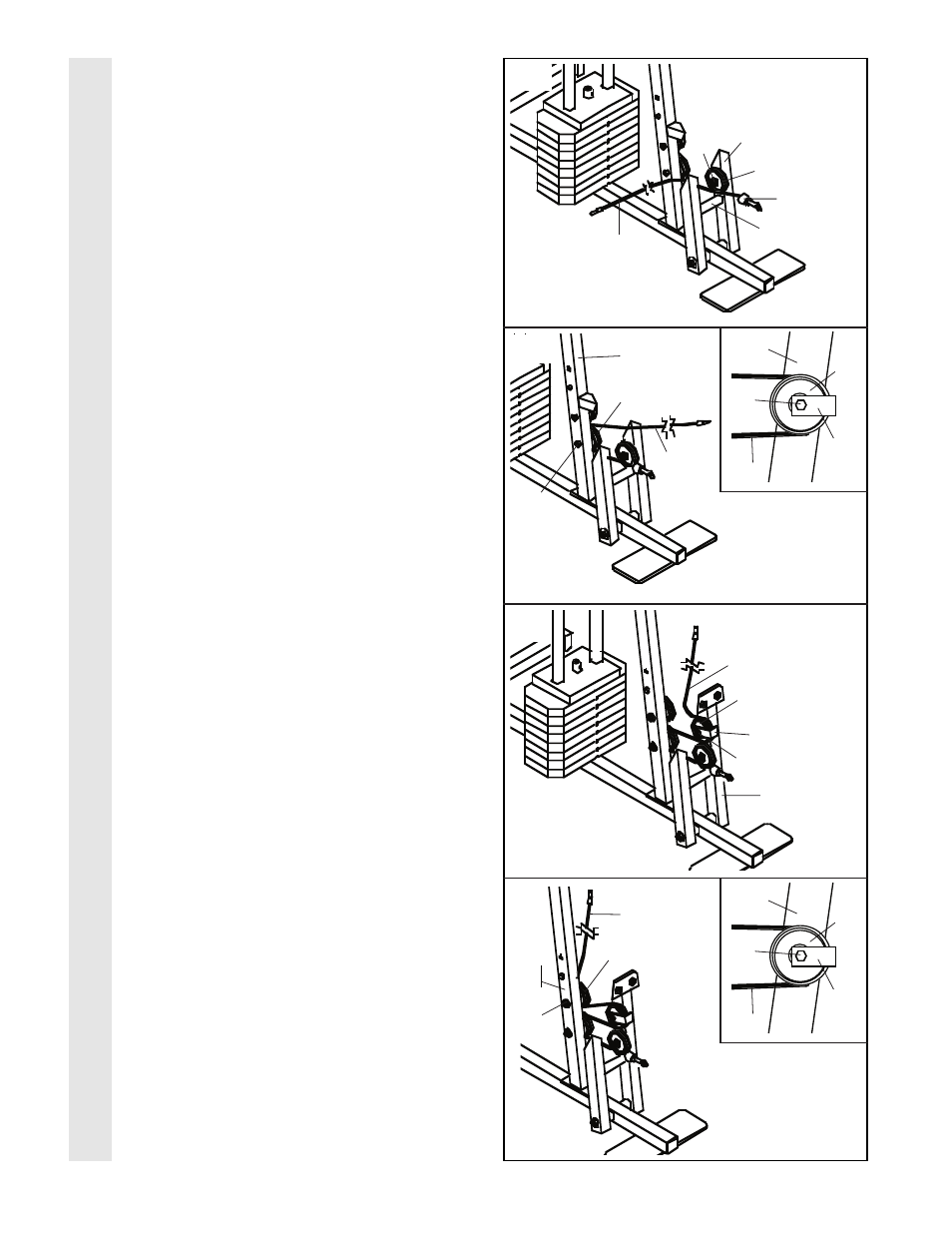
Locate the Medium Cable (58). Route the
Medium Cable (58) under the 3 1/2” Low
Pulley (92) attached to the lower hole in the
Press Frame (17).
Be sure that the end of
the Cable with the ball is on the indicated
side of the Press Frame and that the Cable
is between the Pulley and the crossbar on
the Press Frame. Tighten the 3/8” Nylon
Locknut (21) and the 3/8” x 3 3/4” Bolt (not
shown).
23. Route the Medium Cable (58) around the
3 1/2” Pulley (15) attached to the lower hole in
the Front Upright (42).
See the inset draw-
ing. Be sure that the Cable Trap (66) is
turned to hold the Cable in place and that
the Cable is routed around the Pulley as
shown. Tighten the 3/8” Nylon Locknut (21)
and the 3/8” x 3 3/4” Bolt (71).
24. Route the Medium Cable (58) around the 3 1/2”
Pulley (15) attached to the upper hole in the
Press Frame (17).
Be sure that the Cable
Trap (66) is turned to hold the Cable in
place and that the Cable is routed around
the Pulley as shown. Tighten the 3/8” Nylon
Locknut (21) and the 3/8” x 3 1/2” Bolt (not
shown).
25. Route the Medium Cable (58) around the 3 1/2”
Pulley (15) attached to the upper hole in the
Front Upright (42).
See the inset drawing.
Be sure that the Cable Trap (66) is turned
to hold the Cable in place and that the
Cable is routed around the Pulley as
shown. Tighten the 3/8” Nylon Locknut (21)
and the 3/8” x 3 3/4” Bolt (71).
12
CABLE ASSEMBL
Y
17
Ball
92
21
71
58
21
58
21
58
Inset shows view
from other side
15
42
42
58
15
66
66
15
71
58
Inset shows view
from other side
42
66
15
15
17
Crossbar
21
42
58