Slant/Fin B-200A User Manual
Page 8
Bobcat Model B-120A and B-200A
8
Removing Jacket Front Panel
1. Turn black screws
1
⁄
4
turn to open position.
2. Remove front panel.
To replace the panel, reverse procedure.
INTEGRATED BOILER CONTROL
The integrated boiler control monitors the status of the
room thermostat, high limit switch, low water cutoff (if
installed), water inlet and outlet sensors, flue gas sensor
and flame sensor. It controls the operation of the circula-
tor, combustion blower, gas valve and spark ignitor. The
boiler control also determines the sequence of operation
and timing for pre and post purge periods, trial for ignition
and lock out.
The control display board provides information on boiler
operation on a mode and temperature display and can be
viewed, programmed and reset with specific push buttons.
Diagnostic information is also provided on the display, to
help determine the cause of boiler failure. (See Figure 9).
BOILER CONTROL AND DISPLAY FEATURES
(See Figure 9)
A. BOILER OPERATION STATUS: “Mode Display”
shows status of boiler operation. (See Table 1).
B. VIEW AND CHANGING TEMPERATURES: Setting
boiler supply water temperature and water tank
temperatures (See Table 2).
Press “Select” button for viewing following different
modes on “Mode Display”
1. While “c” is blinking, boiler supply water
temperature for space heating may be set to
desired temperature. The setting range is between
90˚ to 185˚F.
2. While “d” is blinking, boiler supply water tempera-
ture for DHW may be set to desired temperature.
The setting range is between 104˚ to 185˚F.
3. While “t” is blinking, DHW tank temperature may be
set to desired temperature (if tank is equipped with
sensor). The setting range is between 104˚ to 185˚F.
4. View actual following temperatures on
“Temperature Display”, Press “Select” button
for selection:
a. Supply water temperature – Select #1 on
“Mode Display”.
b. Return water temperature – Select #2 on
“Mode Display”.
c. Domestic hot water tank temperature (if tank
equipped with sensor) – Select #3 on
“Mode Display”.
d. Flue gas temperature – Select #4 on
“Mode Display”.
e. Outside temperature (if outside sensor is used)
– Select #5 on “Mode Display”.
C.
Display Board Pushbuttons:
1.
Reset - Used to clear a Lockout Error
(indicated with an “A” in the “Mode Display”)
2.
Select - Used to scroll through the modes in the
“View and Changing Temperatures” and
“Viewing and Changing System Setting” menus.
3.
Enter - Used to store values that are changed in
the “View and Changing Temperatures” and
“Viewing and Changing System Setting” menus.
4.
Up - Used to increase values in the “View and
Changing Temperatures” and “Viewing and
Changing System Setting” menus.
5.
Down - Used to decrease values in the “View and
Changing Temperatures” and “Viewing and
Changing System Setting” menus.
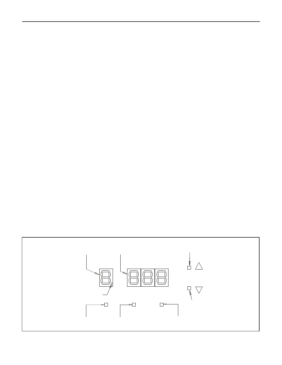
“MODE”
DISPLAY
“BURNER STATUS”
STEADY DOT = BURNER ON
BLINKING DOT = BURNER OFF
MODE
“TEMPERATURE”
DISPLAY
(3 DIGITS)
TEMPERATURE
“UP”
PUSH BUTTON
“DOWN”
PUSH BUTTON
“ENTER”
PUSH BUTTON
“SELECT”
PUSH BUTTON
“RESET”
PUSH BUTTON
RESET
SELECT
ENTER
Figure 9. Display Board