Schumacher Automatic SC-8010A User Manual
Page 5
• 4 •
When disconnecting the charger, turn all switches to off, disconnect the AC cord, remove
6.8
the clip from the vehicle chassis and then remove the clip from the battery terminal.
See CALCULATING CHARGE TIME for length of charge information.
6.9
FOLLOW THESE STEPS WHEN BATTERY IS OUTSIDE VEHICLE
7.
A SPARK NEAR THE BATTERY MAY CAUSE A
BATTERY EXPLOSION. TO REDUCE THE RISK
OF A SPARK NEAR THE BATTERY:
Check the polarity of the battery posts. The
7.1
POSITIVE (POS, P, +) battery post usually has a
larger diameter than the NEGATIVE (NEG, N, -)
post.
Attach at least a 24-inch (61 cm) long 6-gauge (AWG) insulated battery cable to the
7.2
NEGATIVE (NEG, N, -) battery post.
Connect the POSITIVE (RED) charger clip to the POSITIVE (POS, P, +) post of the
7.3
battery.
Position yourself and the free end of the cable you previously attached to the NEGATIVE
7.4
(NEG, N, -) battery post as far away from the battery as possible – then connect the
NEGATIVE (BLACK) charger clip to the free end of the cable.
Do not face the battery when making the final connection. As stated in 7.4, face away
7.5
from the battery when connecting the negative clip to the cable.
Connect charger AC supply cord to electrical outlet.
7.6
When disconnecting the charger, always do so in the reverse order of the connecting
7.7
procedure and break the first connection while as far away from the battery as practical.
A marine (boat) battery must be removed and charged on shore. To charge it onboard
7.8
requires equipment specially designed for marine use.
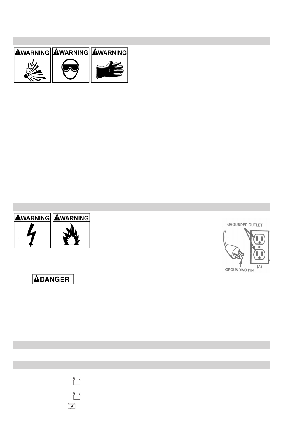
GROUNDING AND AC POWER CORD CONNECTIONS
8.
RISK OF ELECTRIC SHOCK OR FIRE.
This battery charger is for use on a
8.1
nominal 120-volt circuit and has a grounded
plug that looks like the plug illustrated. The
charger must be grounded to reduce the risk of
electric shock. The plug must be plugged into
an outlet that is properly installed and grounded in accordance with
all local codes and ordinances. The plug pins must fit the receptacle
(outlet). Do not use with an ungrounded system.
8.2
Never alter the AC cord or plug provided – if it does not fit the outlet,
have a proper grounded outlet installed by a qualified electrician. An improper
connection can result in a risk of an electric shock or electrocution.
NOTE: Pursuant to
Canadian Regulations, use of an adapter plug is not allowed in Canada. Use of an
adapter plug in the United States is not recommended and should not be used.
Recommended minimum AWG size for extension cord:
8.3
100 feet (30.5 meters) long or less - use an 12 gauge (3.31 mm
•
2
) extension cord.
Over 100 feet (30.5 meters) long - use a 10 gauge (5.26 mm
•
2
) extension cord.
ASSEMBLY INSTRUCTIONS
9.
Remove all cord wraps and uncoil the cables prior to using the battery charger.
CONTROL PANEL
10.
LED Indicators
CONNECTED
(yellow) LED lit: Indicates that the charger is properly connected to
the battery.
CONNECTED
(yellow) LED flashing: Indicates the charger is in abort mode.
CHARGING (yellow) LED lit: Indicates the charger has detected a battery and is
charging it.