Refrigerant flow diagram, 1. refrigerant flow diagram – Sanyo CH1852 User Manual
Page 22
18
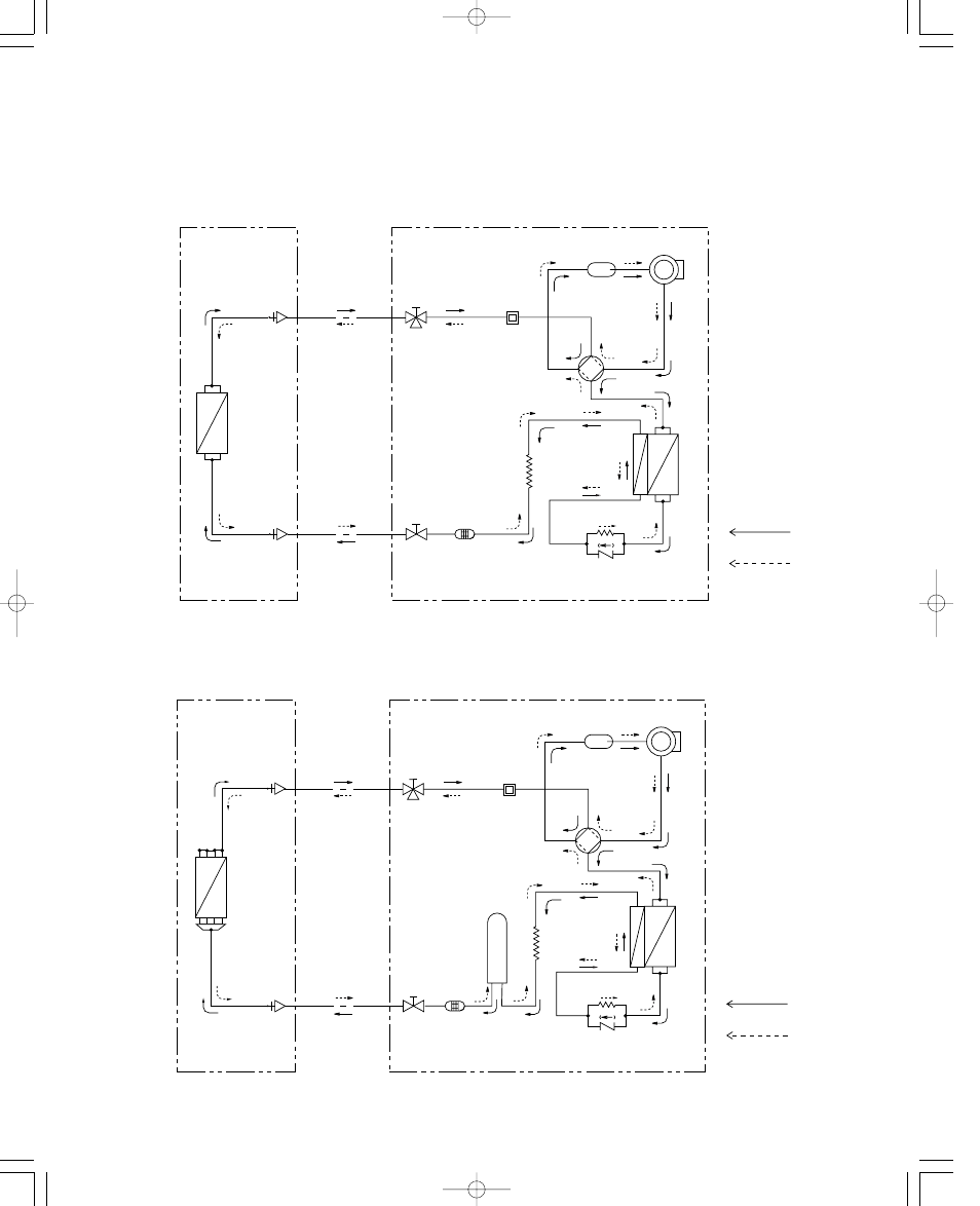
4. REFRIGERANT FLOW DIAGRAM
4-1. Refrigerant Flow Diagram
Indoor unit
KHS0951 / KHS1251
Outdoor unit
CH0951 / CH1251
Compressor
4-way
valve
Accumulator
Wide tube
service
valve
Wide tube
O.D.
3/8" (ø9.52 mm)
1/2" (ø12.7 mm)
Narrow
tube
service
valve
Narrow tube
Heat exchanger
Heat exchanger
Muffler
Capillary
tube
Strainer
Cooling cycle
Heating cycle
Indoor unit
Outdoor unit
O.D.
1/4" (øø6.35 mm)
Capillary tube
Check
valve
Indoor unit
KHS1852
Outdoor unit
CH1852
Compressor
4-way
valve
Accumulator
Wide tube
service
valve
Wide tube
O.D.
5/8" (ø15.88 mm)
Narrow
tube
service
valve
Narrow tube
Heat exchanger
Muffler
Capillary
tube
Strainer
Cooling cycle
Heating cycle
Indoor unit
Outdoor unit
O.D.
1/4" (øø6.35 mm)
Capillary tube
Check
valve
Heat exchanger
Receiver
tank
000-111
SM
(18-68)
00.3.17
11:49
AM
y [ W 18