2 routing to host based network adapters, 3 routing to bm85 bridge/multiplexers – Schneider Electric Modbus Plus Network Bridge Multiplexer none User Manual
Page 29
Device Addressing and Message Routing
31007492
19
2.1.2
Routing to Host Based Network Adapters
For host based network adapters, the byte following the adapter's
network node address specifies a task number (1 ... 8) to which the
message is assigned. Subsequent bytes are not checked by the adapter,
and are available for custom use to the application - for example, for
message counts or status information.
2.1.3
Routing to BM85 Bridge/Multiplexers
Routing to Serial Ports on BM85 Programmable Models
For the programmable models, the user application stored in the BM85
defines the addressing between Modbus Plus and the serial ports.
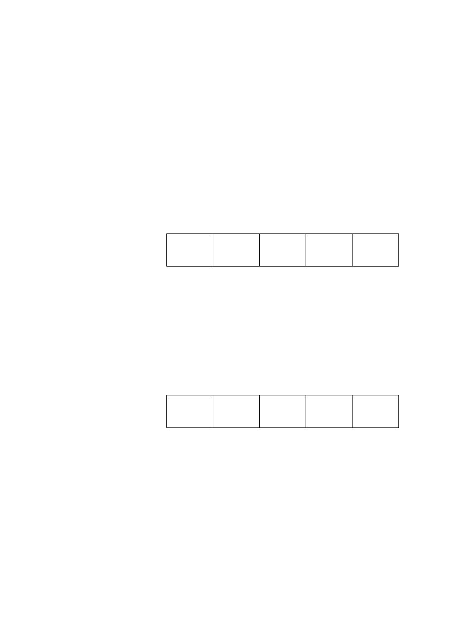
Routing to a Single Slave Device on BM85 Modbus Models
For a single slave device at a Modbus port, two bytes are used to address
the device. The next-to-last non-zero byte addresses the BM85 node
(1 ... 64). The last non-zero byte specifies the Modbus port (1 ... 4), and
therefore specifies the single slave device.
Figure 5 shows an example of routing to a single slave device.
BP85
ADDRESS
(1 ... 64)
BM85
ADDRESS
(1 ... 64)
BM85
PORT
(1 ... 4)
ZERO
ZERO
Figure 5
Modbus Plus Routing to Single Modbus Slave
Routing to a Networked Slave Device on BM85 Modbus Models
For a slave device on a Modbus network at a Modbus port, three bytes
are used to address the device. The third byte from the last non-zero
byte addresses the BM85 node (1 ... 64). The next-to-last non-zero
byte specifies the Modbus port (1 ... 4). The last non-zero byte specifies
the Modbus address of the slave device (1 ... 247).
Figure 6 shows an example of routing to a networked slave device.
BP85
ADDRESS
(1 ... 64)
BM85
ADDRESS
(1 ... 64)
BM85
PORT
(1 ... 4)
ZERO
SLAVE
ADDRESS
(1 ... 247)
Figure 6
Modbus Plus Routing to Networked Modbus Slave