Sony Ericsson GR64 User Manual
Page 56
LZT 123 1834
56
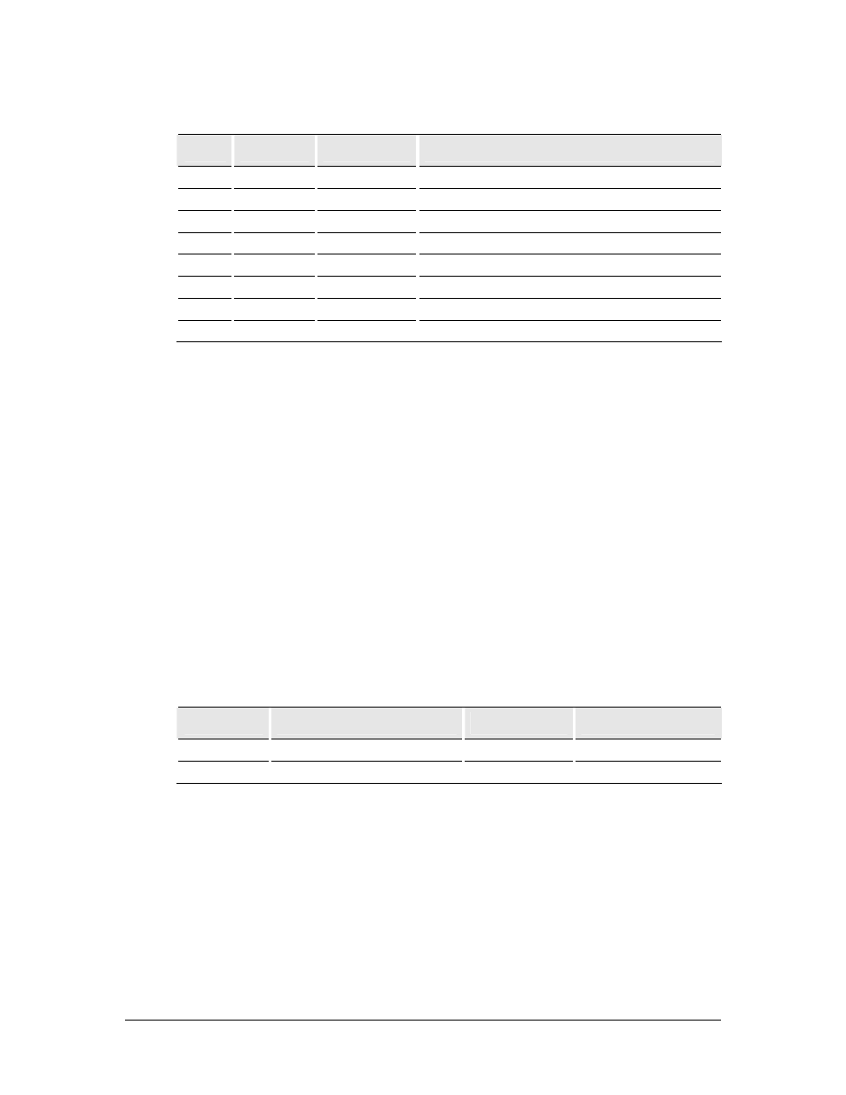
5.11.1 UART1
Pin
Name
Direction
Function
32
DSR1
Output
Data Set Ready (UART1)
36 RI
Output Ring
Indicator
37
DTR1
Input
Data Terminal Ready (UART1)
38
DCD1
Output
Data Carrier Detect (UART1)
39
RTS1
Input
Ready To Send (UART1)
40
CTS1
Output
Clear To Send (UART1)
41
DTM1
Input
Data To Module from host (UART1)
42
DFM1
Output
Data From Module to host (UART1)
UART1 is a full featured Universal Asynchronous Receiver Transmitter providing full-
duplex asynchronous communication.
UART1 has the following features:
•
32 bytes of FIFO for both receive and transmit
•
FIFO threshold interrupts
•
1 start bit, 7 or 8 data bits, 1 optional parity bit, 1 or 2 stop bits
•
Programmable baud rate
•
Auto-configuration mode with auto-baud and auto-format operation
•
Hardware flow control
•
Software flow control.
UART1 signals replicate a 9-pin RS232 (V.24) serial port. However, UART1 signal
levels are not compliant with the RS232 (V.28) standard. Conversion between the
wireless modem CMOS levels and RS232 levels can be achieved using a standard
interface IC, such as the Maxim Integrated Products MAX3237. The relationship
between the levels is shown in the following table:
DTM, DFM
RI,RTS,CTS,DSR,DTM,DCD
RS232 level
GR64 level
1 OFF <-3V
VREF-0.4V
0 ON >+3V
0.4V
5.11.2 Serial Data Signals (DTM1, DFM1)
The default baud rate of the UARTs is auto-baud. Baud rates of between 600 bauds
to 460 kbauds are possible. The wireless modem also supports 3GPP TS 27.010
multiplexing protocol, which starts when the appropriate command is sent.