Sony Ericsson GR64 User Manual
Page 53
LZT 123 1834
53
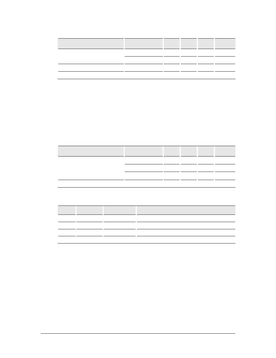
Parameter
Conditions
Min
Typ
Max
Unit
max input gain
14
16
18
mVrms
Input voltage full scale
min input gain
45
50
56
mVrms
Frequency response
-3dB cut-off
300
3400
Hz
Output dc bias level
2.16
2.4
2.64
V
5.9.4 Speaker Signals (EARP, EARN)
EARP and EARN are the speaker output signals. These are differential-mode outputs.
With a full-scale PCM input to the CODEC, 0 dB audio output gain setting, and a
differential load RL = 30Ω, the output voltage between EARP and EARN is 1.5 V rms.
For load resistances less than 30Ω, the full-scale output needs is limited using the
modules internal programmable gain attenuator.
The electrical characteristics are given in the table below.
Parameter
Conditions
Min
Typ
Max
Unit
RL = 30Ω 1.34 1.5 1.68 Vrms
RL = 16 Ω 1.41 Vrms
Input voltage full scale
RL = 8
Ω
1.24 Vrms
Frequency response
-3dB cut-off
300
3400
Hz
5.10 PCM Digital Audio (SSP)
Pin
Name
Direction
Function
48
SSPDFM
Output
Serial PCM data from module to host
47
SSPDTM
Input
Serial PCM data to module from host
51
SSPFS
In/Out
Serial PCM frame synchronization
52 SSPCLK
In/Out Serial
PCM
clock
The SSP (Synchronous Serial Port) digital interface is configured to provide a PCM
(digital) audio interface. This interface can be used to process PCM digital audio
signals as an alternative to routing signals to the CODECs through the analogue
uplink and downlink chains.
5.10.1 PCM Data Format
The PCM digital audio interface for GR64 is based upon the Texas Instruments SSI
standard. The SSP is a versatile interface which can be programmed for different
clock rates and data frame sizes between 4 to 16 bits.