Sony Ericsson GR64 User Manual
Page 12
LZT 123 1834
12
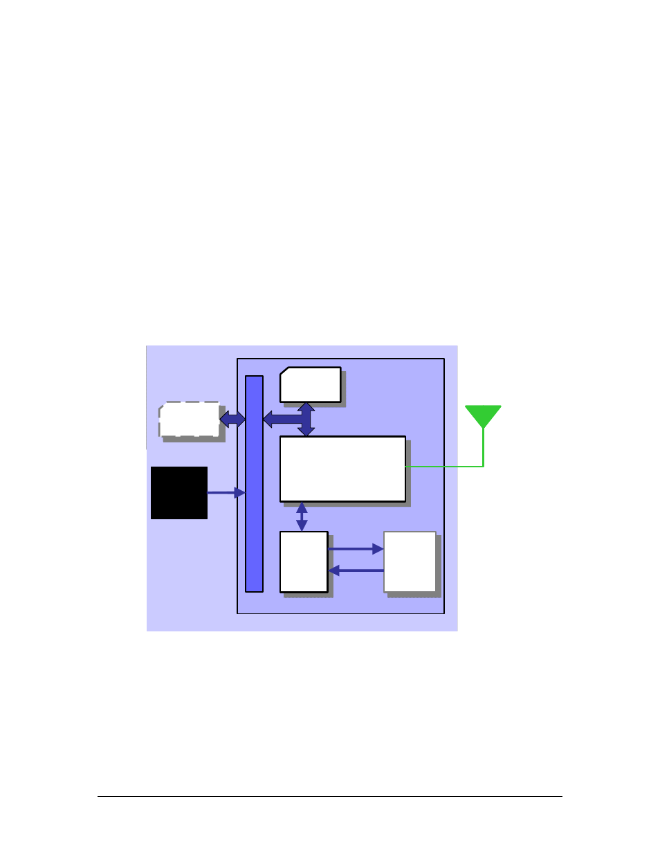
2.2 Wireless modems in a Communication System
Figure
2.2-1 and
Figure
2.2-2 illustrate the main blocks of a wireless communication
system using the wireless modem.
Figure
2.2-1 shows the communication system
when the script is embedded on the wireless modem and
Figure
2.2-2 shows the
communication system when a micro-controller is used. They also show the
communication principles of the system and the interface between the wireless
modem and the application. The definitions in the figures, as used elsewhere in this
manual, are in accordance with the recommendations of 3GPP TS 27.007.
The MS (mobile station) represents the wireless modem and SIM card. The wireless
modem excluding SIM card, is known as the ME (mobile equipment).
The DTE (data terminal equipment) is the controlling application. This can be either
an external host or an internal embedded application.
The DCE (data circuit terminating equipment) is the serial communication interface of
the MS.
SIM
SIM
GSM
ENGINE
GSM
ENGINE
DCE
DCE
DTE
DTE
SY
ST
E
M
IN
T
E
R
F
AC
E
DC
POWER
STATUS &
RESPONSE
COMMAND
& CONTROL
EMBEDDED
APPLICATION
MS
GSM
NETWORK
SIM
SIM
GSM
ENGINE
GSM
ENGINE
DCE
DCE
DTE
DTE
SY
ST
E
M
IN
T
E
R
F
AC
E
DC
POWER
STATUS &
RESPONSE
COMMAND
& CONTROL
EMBEDDED
APPLICATION
MS
GSM
NETWORK
Figure 2.2-1 Main Blocks in a Wireless System (embedded application)