Sony Ericsson GR64 User Manual
Page 47
LZT 123 1834
47
5.8 Powering the Module ON and OFF (ON/OFF)
Pin
Name
Direction
Function
14
ON/OFF
Input
Device on/off control
5.8.1 Turning the Module On
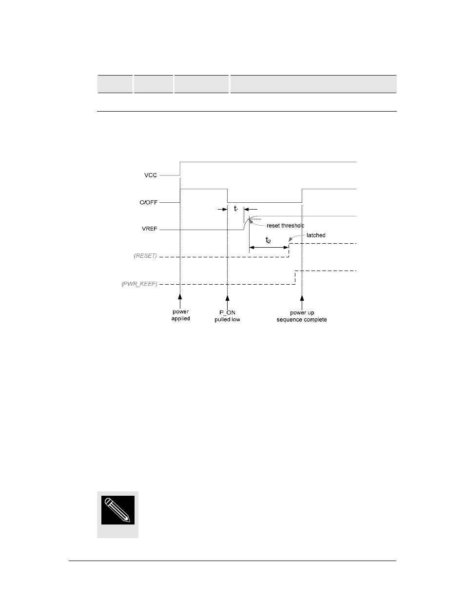
Figure 5.8-1 Power On timing
The GR64 power ON sequence is shown above. The significant signals are VCC,
ON/OFF and VREF, shown by solid lines. The other signals (in dashed lines) are
internal to the module and are shown for reference purposes only.
Initially, power is supplied to the VCC pins. The presence of power raises the
ON/OFF through a pull-up resistor to VCC potential. In order to power the module,
ON/OFF is pulled to ground. Once ON/OFF has been held low for 125ms (denoted by
t
1
) the primary LDOs power up; the VREF signal comes from one of the primary LDOs.
For module variants where VREF supplies a reference voltage to the host, it acts as a
useful indicator that the baseband is powered.
When the VREF is configured as an input, it cannot be used as a power
indicator.
NOTE