4-3. installing the hk-psu04 – Sony DVS-9000-C User Manual
Page 15
1-7
DVS-9000/9000SF
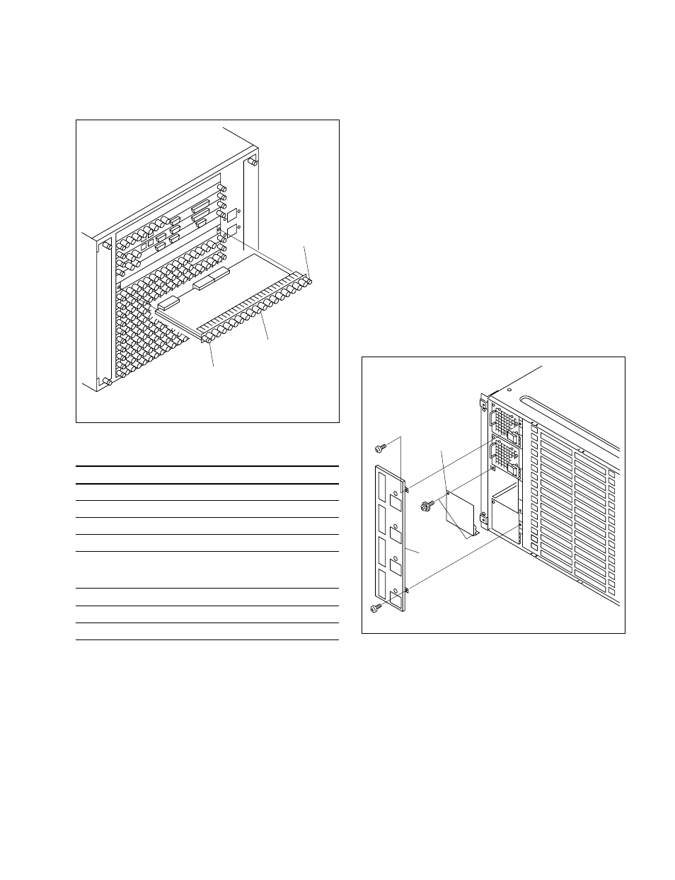
2.
Insert the connector board horizontally level and
secure it with the two fixing screws.
DVS-9000 option
Name of option
Name of board
Slot on the rear side
BKDS-9160
CNO-19 board
16, 17
BKDS-9161
CNO-20 board
8
MKS-8110SD
CNI-10 board
11, 12, 13
MKS-8111SD
CNI-17 board
9
DVS-9000SF option
Name of option
Name of board
Slot on the rear side
MKS-8110SD
CNI-10 board
8
BKDS-9162
CNO-19 board
6
Connector board
Screws
(with drop-safe)
Screws
(with drop-safe)
1-4. Installing the Options
1-4-3. Installing the HK-PSU04
The HK-PSU04 is used after it is installed in the DVS-
9000/9000SF.
n
Before installing the HK-PSU04, be sure to turn off the
main power. If the HK-PSU04 is installed while the main
power is turned on, it can result in electrical shock or
damage to printed circuit boards.
Installation procedure
1.
Remove the front panel of the DVS-9000/9000SF.
(Refer to Section 1-4-1.)
2.
Remove the two screws (B3
x 5) fixing the PS cover,
and remove the PS cover.
3.
Remove the two screws (PSW3
x 6) fixing the blank
panel to the location where the HK-PSU04 is going to
be installed. Then remove the blank panel.
n
Store the removed blank panel in a safe place.
Blank panel
PS cover
PSW
3
x 6
B3
x 5
B3
x 5
(The illustration shows the DVS-9000.)
(The illustration shows the DVS-9000.)