Output terminals, Sw out terminal, Remote jack – Sanyo TLS-224P User Manual
Page 27
OUTPUT TERMINALS
SW OUT Terminal
When recording, a pulse signal is output at the SW
OUT terminal.
This terminal is usually connected to the switch input
(SW IN) of devices like a camera switcher unit, or a
quad compressor.
SW OUT Terminal Output Setting
1
Press the AUDIO ON/MENU button until the (SET
UP 4) menu is displayed.
°
The FIELD (or FRAME) setting is flashing.
NOTE:
•
If “TIMING” is set to FRAME (see step
4
),
“FRAME” will be indicated instead of “FIELD”.
2
Press the
l
(or
j
) button, to set the pulse signal
interval.
Available settings are:
FIELD . . . . . . . . . . 01, 02, 03, 04, 05, 10, 30 or
60 field
FRAME . . . . . . . . . 01, 02, 03, 04, 05, 10, 30 or
60 frame
3
Press the
]
button to select the output timing.
4
Press the
l
(or
j
) button, to set “FIELD” or “FRAME”.
FIELD . . . . . . . . . . 1 pulse is output after each
set number of fields.
FRAME . . . . . . . . . 1 pulse is output after each
set number of frames.
5
Press the
]
button.
°
The “3H” setting starts flashing.
6
Press the
l
(or
j
) button, to set the “3H”.
Y . . . . . . . . . . . . . . When recording in 3-hour
mode, a pulse signal is
output.
N . . . . . . . . . . . . . . When recording in 3-hour
mode, a pulse signal is not
output.
7
Press the PAUSE/SCAN button, the normal screen
is displayed.
REMOTE Jack
•
You can use a VA-RMN01 Remote Control Unit (sold
separately) to control remotely the VCR.
•
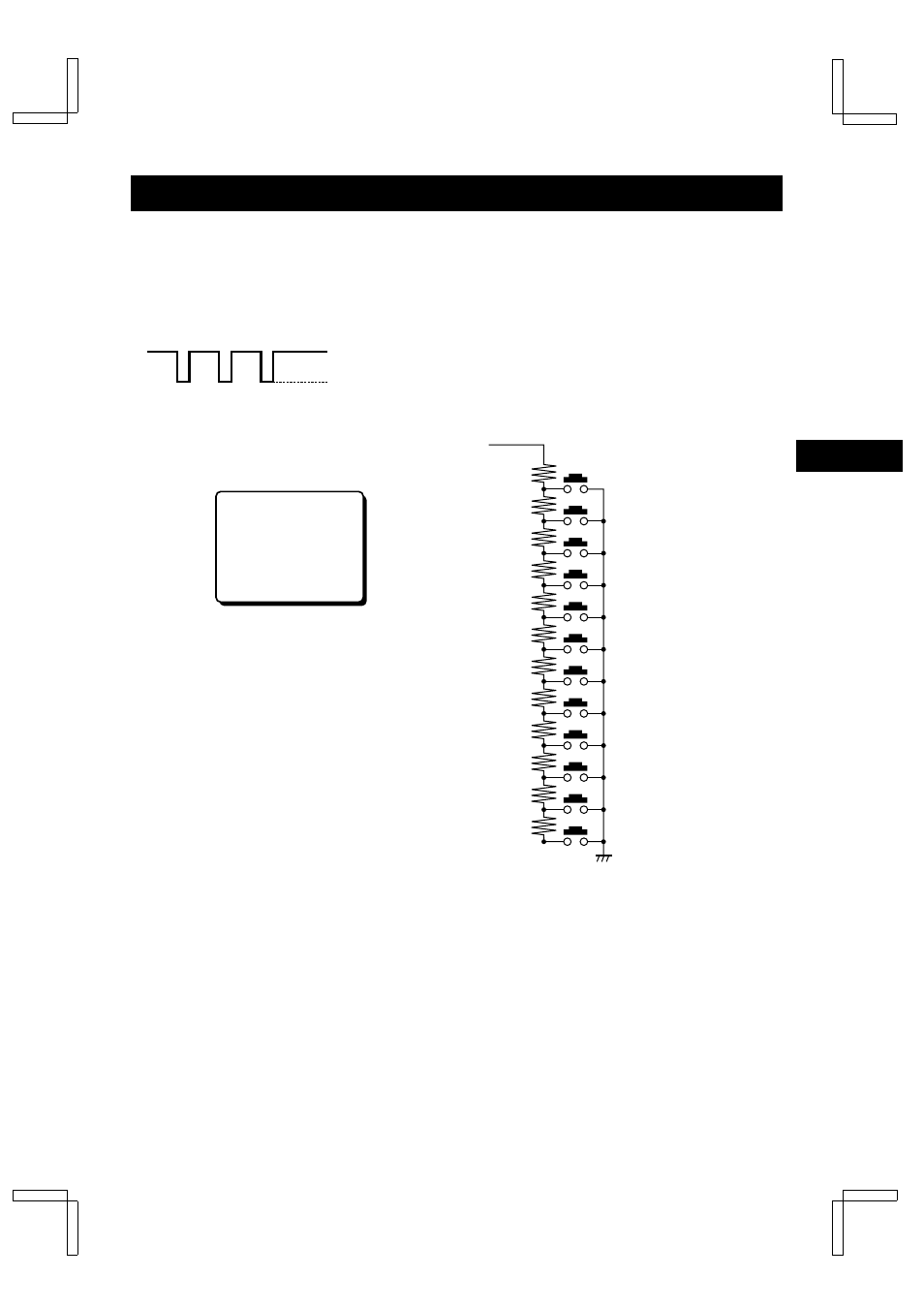
Remote control of the VCR is possible by connecting
a remote controller with a circuit such as indicated
below, to the REMOTE jack.
NOTES:
•
Use a 3.5 mm mini-jack type plug.
•
The connection should be done using a shielded
cable no more that 5 meters long.
NOTES:
•
The functions not available on the VCR will not
operate.
•
The REC/PLAY SPEED
j
button on the VA-RMN01
will function as the TIMER button on the VCR.
5V (H)
0V (L)
(Output impedance: 5.7 k
Ω
)
öSW OUT
FIELD 01
TIMING FIELD
3H Y
VIDEO 00000H
POWER 00000H
Remote control circuit
The resistance tolerance is
2% or less.
SW2: PAUSE/STILL
SW3: REW
SW4: FF
SW5: PLAY
SW6: REC
SW7: MENU
SW8: Do not use
SW1: STOP
SW9: TIMER,
j
SW10: REC/PLAY SPEED,
l
SW11: TRACKING/V.STILL –,
]
SW12: TRACKING/V.STILL +,
«
R2 0.43K
R3 0.51K
R4 0.62K
R5 0.75K
R6 0.91K
R7 1.1K
R8 1.3K
R1 1.5K
R9 2.0K
R10 2.4K
R11 3.6K
R12 5.6K
GB
NE4QG/EX (TLS-224P GB) Mon. May, 11/1998
26
English