Sub-Zero 424/O User Manual
Page 28
Dimensions in parentheses are in
millimeters unless otherwise specified.
28
Home Alarm
Connections
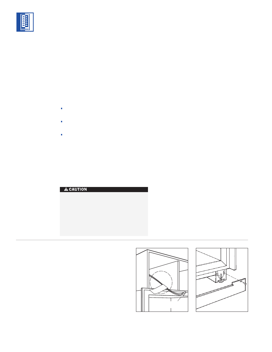
Illus. 7
Illus. 8
M O D E L 4 3 0
I N S T A L L A T I O N I N S T R U C T I O N S
K I C K P L AT E
A N D
G R I L L E
After the unit has been leveled, make sure the
drain pan is installed properly and install the
kickplate. Refer to illustration 8 below.
IMPORTANT NOTE: The kickplate must be
removed for servicing. The floor cannot inter-
fere with removal. Refer to label mounted on
the kickplate support for height clearance.
IMPORTANT NOTE: The floor under the Wine
Storage unit must be at the same level as the
surrounding finished floor to allow for removal
of the unit for servicing.
Replace the grille by reversing the procedure
outlined on page 26. If you’re using a panel
grille, see Overlay Grille Panel on page 31.
Turn power back on to the electrical outlet.
H O M E A L A R M
C O N N E C T I O N S
Before the kickplate and grille are installed, all
necessary wiring connections in the compres-
sor compartment should be completed.
If a home alarm system is to be installed on
the Wine Storage unit, the connections should
be made using the logic supplied with the
alarm specifications. See illustration 7 below
for the appliance lead locations, and refer to
the following for color codes:
Normally open contacts – white with red
stripe wire
Normally closed contacts – white with blue
stripe wire
Common – gray with white stripe wire
Use the
1
/
4
" (6) spade terminals or wire nuts
provided to make the proper wiring connec-
tions.
IMPORTANT NOTE: If you are not responsible
for alarm system connection, this information
should be supplied to the home security
system contractor.
The alarm circuit in the unit is intended as
a low-voltage, low-current device only. It
should not be used to switch line power.
Any unused terminals should be
completely insulated and all wires should
be secured away from conductive or
moving components.
M O D E L
4 3 0