Schumacher SCF-200A User Manual
Page 3
3
LED Display
11.2
CHECK BATTERY
(red) LED lit: Indicates the battery is not properly
connected to the charger.
CHECK BATTERY
(red) LED blinking: Indicates the charger is in abort
mode.
CHARGING
(yellow) LED lit: Indicates the charger is charging the
battery.
CHARGED
(green) LED lit: Indicates the battery is fully charged and the
charger is in maintain mode
.
NOTE: See the Operating Instructions section for a complete description of the
charger modes.
OPERATING INSTRUCTIONS
12.
Charging
Ensure that all of the charger components are in place and in good
1.
working condition, including the plastic boots on the battery clips.
Connect the battery following the connection instructions described in
2.
Using the Quick-Disconnect Cable Connectors section.
Set the Amp/Volt Selector Switch to the proper setting for the battery
3.
being charged.
Connect the AC power following the precautions listed in Section 8.
4.
If you’ve connected everything correctly, the CHARGING
5.
(yellow)
LED should be lit indicating that the charger is charging. If the CHARG-
ING
(yellow) LED does not light or if the CHECK BATTERY
(red) LED is lit, check the connections or have the battery checked/
replaced.
NOTE: This charger is equipped with an auto-start feature. It will not supply
current to the battery clips until a battery is properly connected. Unlike tradi-
tional chargers, the clips will not spark if touched together.
USING THE QUICK-DISCONNECT CABLE CONNECTORS
Connect any of the three output cable assemblies to the charger in seconds.
Make sure to place the charger on a dry, non-flammable surface like metal or
concrete.
NOTE: Never connect the clamp and ring terminal connectors together for use
in other applications, such as external battery or other power source charging,
or to extend the output cable length, as reverse polarity and/or overcharge
conditions will occur.
50 amp Battery Clips
Connect the end of the 50 amp battery clips cable Quick-Connect to the
1.
charger.
Follow the steps in sections 6 and 7 to connect the output clips to the
2.
battery.
After a good electrical connection is made to the battery, plug the power
3.
cord into a 3-prong grounded 120V AC electrical wall outlet. Make
sure to place the charger on a dry, non-flammable surface like metal or
concrete.
Permanent Ring Connectors
The ring connectors permanently attach to the battery providing easy access
to quickly charge your battery. This application is appropriate for motorcycles,
lawn tractors, ATVs and snowmobiles.
To permanently attach to a battery, loosen and remove each nut from
1.
the bolt at the battery terminal.
Connect the red POSITIVE ring connector ring to the POSITIVE battery
2.
terminal.
Connect the black NEGATIVE connector ring to the NEGATIVE battery
3.
terminal.
Replace and tighten the nuts to secure.
4.
Connect the end of the ring terminal cable Quick-Connect to the char-
5.
ger. Take care to keep the wires and plug away from metal and moving
parts.
Plug the charger power cord into a 3-prong grounded 120V AC electrical
6.
wall outlet. Make sure to place the charger on a dry, non-flammable
surface like metal or concrete.
12V ACCESSORY PLUG
Charge or maintain your battery without lifting the hood.
Connect the end of the 12V Accessory Plug Cable Quick-Connect to the
1.
charger.
Insert the 12V accessory plug into the 12V accessory outlet.
2.
Route the power cord from charger through the vehicle’s open window.
3.
Plug the charger power cord into a 3-prong grounded 120V AC electrical
4.
wall outlet. Make sure to place the charger on a dry, non-flammable
surface like metal or concrete.
Battery Connection Indicator
If the charger does not detect a properly connected battery, the CHECK BAT-
TERY
(red) LED will light continuously until such a battery is detected.
Charging will not begin while the CHECK BATTERY
(red) LED is on..
Completion of Charge
Charge completion is indicated by the CHARGED
(green) LED. When
lit, the charger has stopped charging and switched to the Maintain Mode of
operation.
Maintain Mode (Float-Mode Monitoring)
When the CHARGED
(green) LED is lit, the charger has started Maintain
Mode. In this mode, the charger keeps the battery fully charged by delivering a
small current when necessary. If the battery voltage drops below a preset level,
the charger will go back into Charge Mode until the battery voltage returns to
the full charge level, at which point the charger will return to Maintain Mode.
The voltage is maintained at a level determined by the 6 volt or 12 volt battery
type selected.
NOTE: The charger automatically switches between Charge Mode and
Maintain Mode as necessary. The CHARGED
(green) LED will cycle on
when the battery is at full charge and off when the voltage drops below a preset
level and the charger goes into Charge Mode. This cycle will continue, and the
CHARGED
(green) LED will stay on for longer periods of time as the bat-
tery becomes more fully charged.
Desulfation Mode
If the battery is left discharged for an extended period of time, it could become
sulfated and not accept a normal charge. If the charger detects a sulfated
battery, the charger will switch to a special mode of operation designed for
such batteries. If successful, normal charging will resume after the battery is
desulfated. Desulfation could take up to 8 hours. If desulfation fails, charging
will abort and the CHECK BATTERY
(red) LED will blink.
Aborted Charge
If charging can not be completed normally, charging will abort. When charging
aborts, the charger’s output is shut off, and the CHECK BATTERY
(red)
LED will blink. To reset after an aborted charge, either disconnect the battery or
unplug the charger.
CALCULATING CHARGE TIMES
13.
This charger adjusts the charging time in order to charge the battery com-
pletely, efficiently and safely.
This battery charger has a rated output of 2 and 4 amperes. This output will
vary with the age and condition of the battery being charged. If the battery has
only been slightly discharged, it can be charged in less than a few hours. The
same battery will take longer to charge if it is very weak.
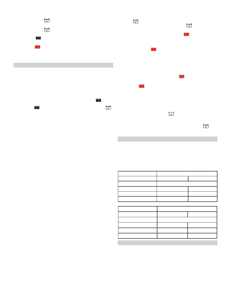
Charging Times
13.1
Battery Condition
2 Amp, 12 Volt Battery
50% Discharged
100% Discharged
Ampere Hour Battery Capacity
Approximate Average Charge Time in Hours
10
3.2
6.2
12
4.0
7.5
20
6.4
12.4
Battery Condition
4 Amp, 6 Volt Battery
50% Discharged
100% Discharged
Ampere Hour Battery Capacity
Approximate Average Charge Time in Hours
10
1.6
3.2
12
2.0
4.0
20
3.2
6.4
MAINTENANCE INSTRUCTIONS
14.
Before performing maintenance, unplug and disconnect the battery charger
14.1
(see Sections 6, 7 and 8).
After use, unplug the charger and use a dry cloth to wipe all battery corro-
14.2
sion and other dirt or oil from the terminals, cords, and the charger case.
Ensure that all of the charger components are in place, securely attached
14.3
and in good working condition, including the plastic boots on the battery
clips.
Servicing does not require opening the unit, as there are no user-service-
14.4
able parts.